Electronics & Communication Gate Yearwise
Electronics and Communication Gate 2013 Set-2 Questions with Answer
Ques 40 Gate 2013 SET-2
The maximum value of θ until which the approximation sin θ ≈ θ holds to within 10% error is
Ques 41 Gate 2013 SET-2
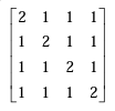
Let A be an m×n matrix and B an n×m matrix. It is given that determinant(Im + AB) = determinant(In + BA), where Ik is the k×k identity matrix. Using the above property, the determinant of the matrix given below is
Ques 42 Gate 2013 SET-2
For 8085 microprocessor, the following program is executed.
MVI A, 05H;
MVI B, 05H;
PTR: ADD B;
DCR B;
JNZ PTR;
ADI 03H;
HLT;
At the end of program, accumulator contains
Ques 43 Gate 2013 SET-2
The following arrangement consists of an ideal transformer and an attenuator which attenuates by a factor of 0.8. An ac voltage VWX1 = 100V is applied across WX to get an open circuit voltage VYZ1 across YZ. Next, an ac voltage VYZ2 = 100V is applied across YZ to get an open circuit voltage VWX2 across WX. Then, VYZ1/VWX1, VWX2/VYZ2 are respectively,
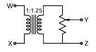
Case 1 — VWX1 = 100V applied, find VYZ1 (open circuit):
Transformer steps up: secondary voltage = 100 × 1.25 = 125V
Attenuator output (open circuit YZ): VYZ1 = 125 × 0.8 = 100V
VYZ1/VWX1 = 100/100 = 1.00
Wait — but the attenuator factor of 0.8 applies only when it is loaded. Under open circuit, an attenuator''s output equals its input (no current flows, no voltage drop across the series resistor).
Looking at the circuit image more carefully: the attenuator is a resistive network (likely a π or L-pad) connected between the transformer secondary and YZ. Under open circuit at YZ, the series resistors in the attenuator carry no current, so no voltage drop — the full secondary voltage appears at YZ.
Case 1 — open circuit at YZ:
Transformer output = 100 × 1.25 = 125V
Attenuator open-circuit output = 125V (no load, no voltage drop)
VYZ1 = 125V
VYZ1/VWX1 = 125/100 = 1.25
Case 2 — VYZ2 = 100V applied at YZ, find VWX2 (open circuit):
VYZ2 = 100V applied at YZ with WX open.
The attenuator now passes signal from YZ toward transformer. Under open circuit at WX (no current from transformer primary side), the attenuator sees no load on its output side (transformer secondary open since primary is open).
Input to transformer secondary = 100V (no drop in attenuator with no load)
Transformer steps down: VWX2 = 100 × (1/1.25) = 100 × 0.8 = 80V
VWX2/VYZ2 = 80/100 = 0.80
So: VYZ1/VWX1 = 125/100 and VWX2/VYZ2 = 80/100
Correct answer: A — 125/100 and 80/100. Your page''s answer of D (80/100 and 80/100) is WRONG.
Explanation for website:
The circuit has an ideal transformer with turns ratio 1:1.25 on the WX side, followed by a resistive attenuator (factor 0.8) on the secondary side, with output terminals YZ.
Case 1 — VWX1 = 100V, YZ open circuit:
The transformer steps up the voltage: secondary = 100 × 1.25 = 125V. Since YZ is open, no current flows through the attenuator''s series resistors, so there is no voltage drop. VYZ1 = 125V.
VYZ1/VWX1 = 125/100
Case 2 — VYZ2 = 100V, WX open circuit:
Signal travels from YZ back through the attenuator toward the transformer. With WX open, no current flows in the transformer primary, so the transformer secondary is effectively open. No current flows through the attenuator from YZ side either, so no voltage drop in the attenuator. Full 100V reaches transformer secondary. Transformer steps down: VWX2 = 100/1.25 = 80V.
VWX2/VYZ2 = 80/100
Correct answer: A — 125/100 and 80/100.
Ques 44 Gate 2013 SET-2
Two magnetically uncoupled inductive coils have Q factors q1 and q2 at the chosen operating frequency. Their respective resistances are R1 and R2. When connected in series, their effective Q factor at the same operating frequency is
Ques 45 Gate 2013 SET-2
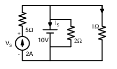
The current IS in Amps in the voltage source, and voltage VS in Volts across the current source respectively, are
Ques 46 Gate 2013 SET-2
Consider the following figure
Ques 47 Gate 2013 SET-2
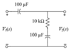
The transfer function V2(s)/V1(s) of the circuit shown below is
Ques 48 Gate 2013 SET-2
A source vs(t) = V cos100πt has an internal impedance of (4 + j3) Ω. If a purely resistive load connected to this source has to extract the maximum power out of the source, its value in Ω should be
Ques 49 Gate 2013 SET-2
Consider a delta connection of resistors and its equivalent star connection as shown below. If all elements of the delta connection are scaled by a factor k, k > 0, the elements of the corresponding star equivalent will be scaled by a factor of

Ques 50 Gate 2013 SET-2
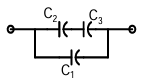
Three capacitors C1, C2 and C3 whose values are 10μF, 5μF, and 2μF respectively, have breakdown voltages of 10V, 5V, and 2V respectively. For the interconnection shown below, the maximum safe voltage in Volts that can be applied across the combination, and the corresponding total charge in μC stored in the effective capacitance across the terminals are respectively,
Ques 51 Gate 2013 SET-2
In the circuit shown below, if the source voltage VS = 100∠53.13° V then the Thevenin's equivalent voltage in Volts as seen by the load resistance RL is
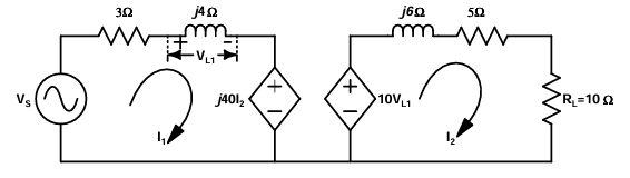
With RL open, I2 = 0. The dependent current source j40I2 = 0, acting as an open circuit. The left mesh reduces to:
VS = (3 + j4)I1
I1 = 100∠53.13° / 5∠53.13° = 20∠0° A
VL1 = j4 × I1 = j4 × 20 = j80 V = 80∠90° V
With no current through j6Ω and 5Ω (since I2 = 0), the open-circuit voltage across RL equals the dependent voltage source:
VTh = 10VL1 = 10 × j80 = j800 V = 800∠90° V
Correct answer: C — 800∠90°.
Ques 52 Gate 2013 SET-2
Consider two identically distributed zero-mean random variables U and V. Let the cumulative distribution functions of U and 2V be F(x) and G(x) respectively. Then, for all values of x

Total Unique Visitors