Electronics & Communication Gate Yearwise
Electronics and Communication Gate 2022 Questions with Answer
Ques 27 Gate 2022
Select the Boolean function(s) equivalent to 𝑥 + 𝑦𝑧, where 𝑥, 𝑦, and 𝑧 are Boolean variables, and + denotes logical OR operation.
Ques 28 GATE 2022
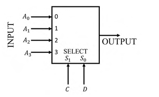
Consider the 2-bit multiplexer (MUX) shown in the figure. For OUTPUT to be the XOR of C and D, the values for A0, A1, A2, and A3 are ____________.
Ques 29 GATE 2022
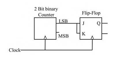
For the circuit shown, the clock frequency is f0 and the duty cycle is 25%. For the signal at the Q output of the Flip-Flop, _______.
Ques 30 GATE 2022
A waveguide consists of two infinite parallel plates (perfect conductors) at a separation of 10−4 cm, with air as the dielectric. Assume the speed of light in air to be 3 × 10⁸ m/s. The frequency/frequencies of TM waves which can propagate in this waveguide is/are _______.
Ques 31 Gate 2022
In a circuit, there is a series connection of an ideal resistor and an ideal capacitor. The conduction current (in Amperes) through the resistor is 2sin(𝑡 + 𝜋/2). The displacement current (in Amperes) through the capacitor is _________.
Ques 32 GATE 2022
In an electrostatic field, the electric displacement density vector, D⃗, is given by
D⃗(x, y, z) = (x3 î + y3 ĵ + xy2 k̂) C/m2,
where î, ĵ, k̂ are the unit vectors along x-axis, y-axis, and z-axis, respectively.
Consider a cubical region R centered at the origin with each side of length 1 m, and vertices at (±0.5 m, ±0.5 m, ±0.5 m). The electric charge enclosed within R is _________ C (rounded off to two decimal places).
Ques 33 GATE 2022
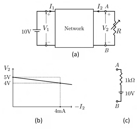
A linear 2-port network is shown in Fig. (a). An ideal DC voltage source of 10 V is connected across Port 1. A variable resistance R is connected across Port 2. As R is varied, the measured voltage and current at Port 2 is shown in Fig. (b) as a V2 versus −I2 plot. Note that for V2 = 5 V, I2 = 0 mA, and for V2 = 4 V, I2 = −4 mA.
When the variable resistance R at Port 2 is replaced by the load shown in Fig. (c), the current I2 is _______ mA (rounded off to one decimal place).
Ques 34 GATE 2022
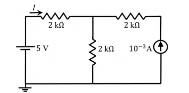
The current I in the circuit shown is ________.
Ques 35 GATE 2022
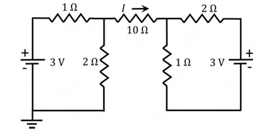
Consider the circuit shown in the figure. The current I flowing through the 10 Ω resistor is _______
Ques 36 GATE 2022
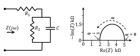
For the circuit shown, the locus of the impedance Z(jω) is plotted as ω increases from zero to infinity. The values of R1 and R2 are:
Ques 37 GATE 2022
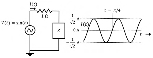
Consider the circuit shown in the figure with input V(t) in volts. The sinusoidal steady state current I(t) flowing through the circuit is shown graphically (where t is in seconds). The circuit element Z can be ________.
Ques 38 GATE 2022
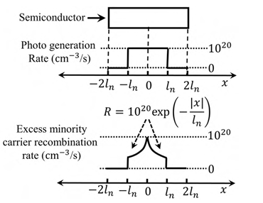
A p-type semiconductor with zero electric field is under illumination (low level injection) in steady state condition. Excess minority carrier density is zero at x = ±2ln, where ln = 10−4 cm is the diffusion length of electrons. Assume electronic charge, q = −1.6 × 10⁻¹⁹ C. The profiles of photo-generation rate of carriers and the recombination rate of excess minority carriers (R) are shown. Under these conditions, the magnitude of the current density due to the photo-generated electrons at x = +2ln is _________ mA/cm2 (rounded off to two decimal places).
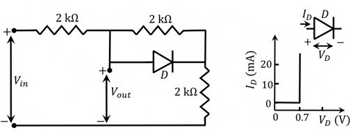
Ques 39 GATE 2022
A circuit and the characteristics of the diode (D) in it are shown. The ratio of the minimum to the maximum small signal voltage gain ∂Vout/∂Vin is ________ (rounded off to two decimal places).

Total Unique Visitors