Electrical Engineering Gate Yearwise
Electrical Gate 2025
Electrical Gate 2024
Electrical Gate 2023
Electrical Gate 2022
Electrical Gate 2021
Electrical Gate 2020
Electrical Gate 2019
Electrical Gate 2018
Electrical Gate 2017 (Set 1)
Electrical Gate 2017 (Set 2)
Electrical Gate 2016 (Set 1)
Electrical Gate 2016 (Set 2)
Electrical Gate 2015 (Set 1)
Electrical Gate 2015 (Set 2)
Electrical Gate 2014 (Set 1)
Electrical Gate 2014 (Set 2)
Electrical Gate 2014 (Set 3)
Electrical Gate 2013 (Set 1)
Electrical Gate 2013 (Set 2)
Electrical Gate 2013 (Set 3)
Electrical Engineering Gate 2026 Questions with Answer
Ques 53 GATE 2026
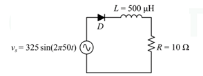
Consider the circuit shown. Assume that the diode D is ideal. The supply voltage vs = 325 sin(2π50t) V, L = 500 µH, and R = 10 Ω. The peak diode current (in amperes) is ______________
(Round off to one decimal place)
Ques 54 GATE 2026
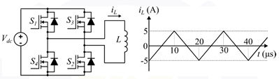
Consider the single-phase voltage source inverter circuit feeding an inductive load (L). Assume that the power MOSFET switches are ideal. S1 and S2 are switched on during the first 10 µs, and S3 and S4 are switched on during the next 10 µs in a switching cycle. The switches in the same leg are thus switched in a complementary fashion. Neglect the dead time. The waveform of the inductor current (iL) in the steady state is triangular with a peak value of 5 A as shown.
The rms value of the current through the switch S1 is:
Ques 55 GATE 2026
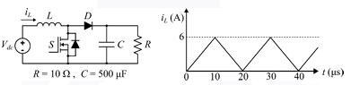
Consider the boost converter circuit shown. Assume that the semiconductor devices are ideal. In steady state, the inductor current rises linearly from 0 A to 6 A in the first 10 µs and then falls linearly from 6 A to 0 A in the next 10 µs of every switching cycle as shown. The load resistance R is 10 Ω and the capacitance C is 500 µF.
Neglect the ripple in the output voltage. What is the input voltage Vdc?
Ques 56 GATE 2026
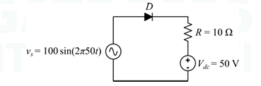
Consider the circuit shown. Assume that the diode (D) is ideal.
Given vs = 100 sin(2π50t) V, Vdc = 50 V, and R = 10 Ω, the average value of the current through the diode is ___________ A
(Round off to two decimal places)
Ques 57 GATE 2026
Consider a power system with N buses, of which P are generator buses and the remaining Q are load buses (where there is no generation).
Assume that there are no reactive power-limit violations at the generator buses.
What is the size of the Jacobian matrix in the Newton-Raphson load flow method?
Ques 58 GATE 2026
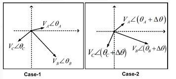
The initial three-phase voltage phasors (V̄A, V̄B, and V̄C) at a bus of a power network are as shown in Case-1. Due to a disturbance, the bus voltage phasors changed in phase by a small angle Δθ, and the magnitudes remained the same as depicted in Case-2.
Which one of the following statements is correct about the zero sequence components?
Ques 59 GATE 2026
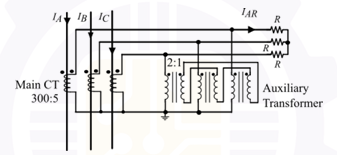
In the circuit shown, the phase currents are IA = 572.812 + j50.115 A, IB = −254.525 − j459.175 A, IC = −207.083 + j444.091 A.
Ques 60 GATE 2026
The operating characteristic of a reactance relay is given by X ≤ 1 Ω, where X is the reactance calculated by the relay. Its operating characteristic in the admittance plane (G-B plane, where G and B denote conductance and susceptance, respectively, expressed in &#herve;) is given by:
Ques 61 GATE 2026
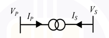
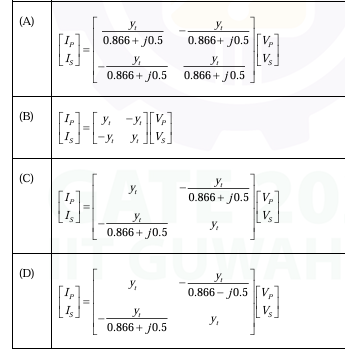
A three-phase two-winding transformer has a voltage transformation ratio VP/VS = 0.866 + j0.5, where VP is the primary side voltage in p.u., and VS is the secondary side voltage in p.u. IP and IS represent the currents injected into the primary and secondary sides of the transformer, respectively. The admittance corresponding to the leakage impedance of the transformer referred to the secondary is yt p.u. Neglect the magnetizing branch.
Ques 62 GATE 2026
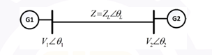
For the balanced 3-phase transmission line shown, consider the following cases:
Case-1: |V1| = 1.1 p.u., |V2| = 0.9 p.u., Z = 0.75∠0° p.u. and θ12 = θ1 − θ2 = 0°
Case-2: |V1| = 1.1 p.u., |V2| = 0.9 p.u., Z = 0.75∠90° p.u. and θ12 = θ1 − θ2 = 90°
Ques 63 GATE 2026
A system with two generators G1 and G2 (without generator limits) is shown. The total load on the system is 1184 MW. The expressions for the cost of generation (C1 and C2) and real power loss (PLoss) are as follows:
C1(PG1) = 1000 + 50PG1 + 0.01(PG1)2 Rs/MWh
C2(PG2) = 2000 + 50PG2 + 0.001(PG2)2 Rs/MWh
PLoss = 0.001(PG2 − 50)2 MW
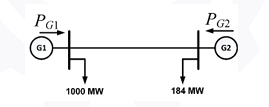
Consider the Lagrange multiplier λ = 70.25 for optimal generation.
Ques 64 GATE 2026
Consider the infinite-length, discrete-time sequence x[n] = 0.9|n|, where n is an integer. The region of convergence of its Z-transform X(z) is given by:
(Note: z is a complex variable)
Ques 65 GATE 2026
Let xc(t) be any continuous-time periodic signal with period T. It is sampled uniformly with a sampling period Ts where Ts ≠ T, resulting in the discrete sequence x[n] = xc(nTs), where n is an integer.
Which one of the following statements is correct about x[n]?

Total Unique Visitors