Electrical Engineering Gate Yearwise
Electrical Gate 2024
Electrical Gate 2023
Electrical Gate 2022
Electrical Gate 2021
Electrical Gate 2020
Electrical Gate 2019
Electrical Gate 2018
Electrical Gate 2017 (Set 1)
Electrical Gate 2017 (Set 2)
Electrical Gate 2016 (Set 1)
Electrical Gate 2016 (Set 2)
Electrical Gate 2015 (Set 1)
Electrical Gate 2015 (Set 2)
Electrical Gate 2014 (Set 1)
Electrical Gate 2014 (Set 2)
Electrical Gate 2014 (Set 3)
Electrical Gate 2013 (Set 1)
Electrical Gate 2013 (Set 2)
Electrical Gate 2013 (Set 3)
Electrical Engineering Gate 2016 Set-2 Questions with Answer
Ques 1 GATE 2016 SET-2
The circuit shown below is an example of a

Ques 2 GATE 2016 SET-2
For the circuit shown below, taking the opamp as ideal, the output voltage Vout in terms of the input voltages V1, V2 and V3 is

Ques 3 GATE 2016 SET-2
The following figure shows the connection of an ideal transformer with primary to secondary turns ratio of 1:100. The applied primary voltage is 100 V (rms), 50 Hz, AC. The rms value of the current I, in ampere, is ________.

Ques 4 GATE 2016 SET-2
A resistance and a coil are connected in series and supplied from a single phase, 100 V, 50 Hz ac source as shown in the figure below. The rms values of plausible voltages across the resistance (VR) and coil (VC) respectively, in volts, are

Ques 5 GATE 2016 SET-2
The voltage (V) and current (A) across a load are as follows.
v(t) = 100sin(ωt)
i(t) = 10sin(ωt-60°) + 2sin(3ωt) + 5sin(5ωt).
The average power consumed by the load, in W, is ________.
Ques 6 GATE 2016 SET-2
In the circuit shown below, the voltage and current sources are ideal. The voltage (Vout) across the current source, in volts, is

Ques 7 GATE 2016 SET-2
The graph associated with an electrical network has 7 branches and 5 nodes. The number of independent KCL equations and the number of independent KVL equations, respectively, are
Ques 8 GATE 2016 SET-2
The driving point input impedance seen from the source VS of the circuit shown below, in Ω, is ________.

Ques 9 GATE 2016 SET-2
The z-parameters of the two port network shown in the figure are z11=40 Ω, z12=60 Ω, z21=80 Ω and z22=100 Ω. The average power delivered to RL=20 Ω, in watts, is ________.

Ques 10 GATE 2016 SET-2
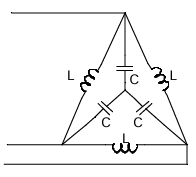
In the balanced 3-phase, 50 Hz, circuit shown below, the value of inductance (L) is 10 mH. The value of the capacitance (C) for which all the line currents are zero, in millifarads, is ________.
Ques 11 GATE 2016 SET-2
In the circuit shown below, the initial capacitor voltage is 4 V. Switch S1 is closed at t=0. The charge (in μC) lost by the capacitor from t=25 μs to t=100 μs is ________.

Ques 12 GATE 2016 SET-2
Consider a linear time-invariant system with transfer function
H(s) = 1/(s+1).
If the input is cos(t) and the steady state output is Acos(t+α), then the value of A is ________.
Ques 13 GATE 2016 SET-2
For the network shown in the figure below, the frequency (in rad/s) at which the maximum phase lag occurs is ________.


Total Unique Visitors