Electrical Engineering Gate Yearwise
Electrical Gate 2024
Electrical Gate 2023
Electrical Gate 2022
Electrical Gate 2021
Electrical Gate 2020
Electrical Gate 2019
Electrical Gate 2018
Electrical Gate 2017 (Set 1)
Electrical Gate 2017 (Set 2)
Electrical Gate 2016 (Set 1)
Electrical Gate 2016 (Set 2)
Electrical Gate 2015 (Set 1)
Electrical Gate 2015 (Set 2)
Electrical Gate 2014 (Set 1)
Electrical Gate 2014 (Set 2)
Electrical Gate 2014 (Set 3)
Electrical Gate 2013 (Set 1)
Electrical Gate 2013 (Set 2)
Electrical Gate 2013 (Set 3)
Electrical Engineering Gate 2021 Questions with Answer
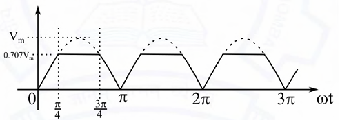
Ques 1 GATE 2021
The waveform shown in solid line is obtained by clipping a full-wave rectified sinusoid (shown dashed). The ratio of the RMS value of the full-wave rectified waveform to the RMS value of the clipped waveform is _______. (Round off to 2 decimal places.)
Ques 2 GATE 2021
A 100 Hz square wave, switching between 0 V and 5 V, is applied to a CR high-pass filter circuit as shown. The output voltage waveform across the resistor is 6.2 V peak-to-peak. If the resistance R is 820 Ω, then the value C is _______ μF. (Round off to 2 decimal places.)

Ques 3 GATE 2021
A three-phase balanced voltage is applied to the load shown. The phase sequence is RYB. The ratio \\frac{|IB|}{|IR|} is

Ques 4 GATE 2021
In the given circuit, for maximum power to be delivered to RL, its value should be _______ Ω. (Round off to 2 decimal places.)

Ques 5 GATE 2021
An air-core radio-frequency transformer as shown has a primary winding and a secondary winding. The mutual inductance M between the windings of the transformer is _______ μH. (Round off to 2 decimal places.)

Ques 6 GATE 2021
For the network shown, the equivalent Thevenin voltage and Thevenin impedance as seen across terminals 'ab' is

Ques 7 GATE 2021
In the given circuit, the value of capacitor C that makes current I=0 is _______ μF.

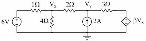
Ques 8 GATE 2021
In the given circuit, for voltage vy to be zero, the value of β should be _______ (Round off to 2 decimal places).
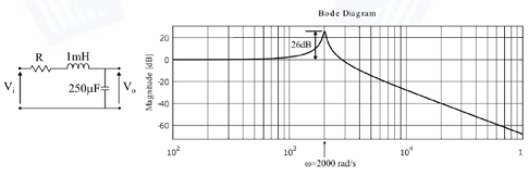
Ques 9 GATE 2021
The Bode magnitude plot for the transfer function Vo(s) / Vi(s) of the circuit is as shown. The value of R is _______ Ω. (Round off to 2 decimal places.)
Ques 10 GATE 2021
A signal generator having a source resistance of 50 Ω is set to generate a 1 kHz sinewave. Open circuit terminal voltage is 10 V peak-to-peak. Connecting a capacitor across the terminals reduces the voltage to 8 V peak-to-peak. The value of this capacitor is _______ F. (Round off to 2 decimal places.)
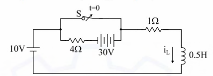
Ques 11 GATE 2021
In the circuit, switch 'S' is in the closed position for a very long time. If the switch is opened at time t = 0, then iL(t) in amperes, for t≥0 is
Ques 12 GATE 2021
The input impedance, Zin(s), for the network shown is

Ques 13 GATE 2021
Consider a closed-loop system as shown. Gp(s) = ¼4.4 / s(1 + 0.1s) is the plant transfer function and Gc(s) = 1 is the compensator. For a unit-step input, the output response has damped oscillations. The damped natural frequency is _______ rad/s. (Round off to 2 decimal places.)


Total Unique Visitors