Electrical Engineering Gate Yearwise
Electrical Gate 2024
Electrical Gate 2023
Electrical Gate 2022
Electrical Gate 2021
Electrical Gate 2020
Electrical Gate 2019
Electrical Gate 2018
Electrical Gate 2017 (Set 1)
Electrical Gate 2017 (Set 2)
Electrical Gate 2016 (Set 1)
Electrical Gate 2016 (Set 2)
Electrical Gate 2015 (Set 1)
Electrical Gate 2015 (Set 2)
Electrical Gate 2014 (Set 1)
Electrical Gate 2014 (Set 2)
Electrical Gate 2014 (Set 3)
Electrical Gate 2013 (Set 1)
Electrical Gate 2013 (Set 2)
Electrical Gate 2013 (Set 3)
Electrical Engineering Gate 2014 Set-2 Questions with Answer
Ques 1 GATE 2014 SET-2
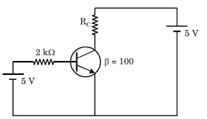
The transistor in the given circuit should always be in active region. Take VCE(sat)=0.2V, VBE=0.7V. The maximum value of RC in kΩ which can be used, is ________.
Ques 2 GATE 2014 SET-2
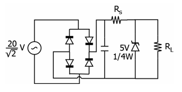
The sinusoidal ac source in the figure has an rms value of 20/√2 V. Considering all possible values of RL, the minimum value of RS in Ω to avoid burnout of the Zener diode is ________.
Ques 3 GATE 2014 SET-2
Assuming the diodes to be ideal in the figure, for the output to be clipped, the input voltage vi must be outside the range

Ques 4 GATE 2014 SET-2
Two identical coupled inductors are connected in series. The measured inductances for the two possible series connections are 380μH and 240μH. Their mutual inductance in μH is ________.
Ques 5 GATE 2014 SET-2
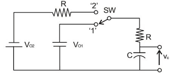
The switch SW shown in the circuit is kept at position '1' for a long duration. At t=0+, the switch is moved to position '2'. Assuming |Vo2| > |Vo1|, the voltage vc(t) across the capacitor is
Ques 6 GATE 2014 SET-2
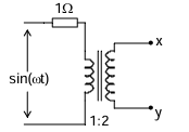
Assuming an ideal transformer, the Thevenin's equivalent voltage and impedance as seen from the terminals x and y for the circuit in figure are
Ques 7 GATE 2014 SET-2
The voltage across the capacitor, as shown in the figure, is expressed as
vc(t) = A1sin(ω1t - θ1) + A2sin(ω2t - θ2).
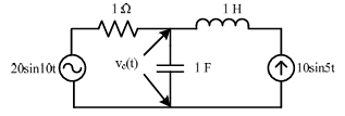
The values of A1 and A2 respectively, are
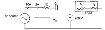
Ques 8 GATE 2014 SET-2
The total power dissipated in the circuit, shown in the figure, is 1 kW. The voltmeter, across the load, reads 200 V. The value of XL is ________.
Ques 9 GATE 2014 SET-2
Consider an LTI system with transfer function H(s) = 1/(s(s+4)). If the input to the system is cos(3t) and the steady state output is Asin(3t+α), then the value of A is
Ques 10 GATE 2014 SET-2
The closed-loop transfer function of a system is T(s) = 4/(s2+0.4s+4). The steady state error due to unit step input is ________.
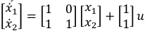
Ques 11 GATE 2014 SET-2
The state transition matrix for the system
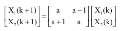
Ques 12 GATE 2014 SET-2
A discrete system is represented by the difference equation
Ques 13 GATE 2014 SET-2
Which of the following is an invalid state in an 8-4-2-1 Binary Coded Decimal counter

Total Unique Visitors