Electrical Engineering Gate Yearwise
Electrical Gate 2024
Electrical Gate 2023
Electrical Gate 2022
Electrical Gate 2021
Electrical Gate 2020
Electrical Gate 2019
Electrical Gate 2018
Electrical Gate 2017 (Set 1)
Electrical Gate 2017 (Set 2)
Electrical Gate 2016 (Set 1)
Electrical Gate 2016 (Set 2)
Electrical Gate 2015 (Set 1)
Electrical Gate 2015 (Set 2)
Electrical Gate 2014 (Set 1)
Electrical Gate 2014 (Set 2)
Electrical Gate 2014 (Set 3)
Electrical Gate 2013 (Set 1)
Electrical Gate 2013 (Set 2)
Electrical Gate 2013 (Set 3)
Electrical Engineering Gate 2015 Set-2 Questions with Answer
Ques 1 GATE 2015 SET-2
The filters F1 and F2 having characteristics as shown in Figures (a) and (b) are connected as shown in Figure (c). The cut-off frequencies of F1 and F2 are f1 and f2 respectively. If f1 < f2, the resultant circuit exhibits the characteristic of a

Ques 2 GATE 2015 SET-2
When a bipolar junction transistor is operating in the saturation mode, which one of the following statements is TRUE about the state of its collector-base (CB) and the base-emitter (BE) junctions?
Ques 3 GATE 2015 SET-2
The saturation voltage of the ideal op-amp shown below is ±10V. The output voltage vo of the following circuit in the steady-state is

Ques 4 GATE 2015 SET-2
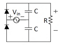
In the following circuit, the input voltage Vin is 100sin(100πt). For 100πRC = 50, the average voltage across R (in Volts) under steady-state is nearest to
Ques 5 GATE 2015 SET-2
The operational amplifier shown in the figure is ideal. The input voltage (in Volt) is Vi = 2sin(2πx2000t). The amplitude of the output voltage Vo (in Volt) is ________.

Ques 6 GATE 2015 SET-2
In the following circuit, the transistor is in active mode and VC = 2V. To get VC = 4V, we replace RC with R'C. Then the ratio R'C/RC is ________.

Ques 7 GATE 2015 SET-2
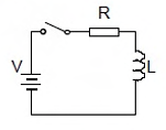
A series RL circuit is excited at t=0 by closing a switch as shown in the figure. Assuming zero initial conditions, the value of d2i/dt2 at t=0+ is
Ques 8 GATE 2015 SET-2
The current i (in Ampere) in the 2Ω resistor of the given network is ________.

Ques 9 GATE 2015 SET-2
Find the transformer ratios a and b such that the impedance (Zin) is resistive and equals 2.5Ω when the network is excited with a sine wave voltage of angular frequency of 5000 rad/s.

Ques 10 GATE 2015 SET-2
In the given network V1=100∠0°V, V2=100∠-120°V, V3=100∠+120°V. The phasor current i (in Ampere) is

Ques 11 GATE 2015 SET-2
A symmetrical square wave of 50% duty cycle has amplitude of ±15V and time period of 0.4π ms. This square wave is applied across a series RLC circuit with R=5Ω, L=10mH, and C=4μF. The amplitude of the 5000 rad/s component of the capacitor voltage (in Volt) is ________.

Ques 12 GATE 2015 SET-2
An open loop control system results in a response of e-2t(sin5t + cos5t) for a unit impulse input. The DC gain of the control system is ________.
Ques 13 GATE 2015 SET-2
Nyquist plots of two functions G1(s) and G2(s) are shown in figure.


Total Unique Visitors