Electrical Engineering Gate Yearwise
Electrical Gate 2025
Electrical Gate 2024
Electrical Gate 2023
Electrical Gate 2022
Electrical Gate 2021
Electrical Gate 2020
Electrical Gate 2019
Electrical Gate 2018
Electrical Gate 2017 (Set 1)
Electrical Gate 2017 (Set 2)
Electrical Gate 2016 (Set 1)
Electrical Gate 2016 (Set 2)
Electrical Gate 2015 (Set 1)
Electrical Gate 2015 (Set 2)
Electrical Gate 2014 (Set 1)
Electrical Gate 2014 (Set 2)
Electrical Gate 2014 (Set 3)
Electrical Gate 2013 (Set 1)
Electrical Gate 2013 (Set 2)
Electrical Gate 2013 (Set 3)
Electrical Engineering Gate 2026 Questions with Answer
Ques 1 GATE 2026
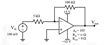
In the circuit shown, the open loop gain of the operational amplifier is A0 = 105.
What is the voltage gain of the circuit?
(Round off to two decimal places)
Ques 2 GATE 2026
The Laplace transform of the step response of a system is given by
Y(s) = 100/(s(s + 100))
The rise time is defined as the time taken for the response to go from 0.1 to 0.9 of its final value. The settling time is defined as the time taken for the response to reach 0.98 of its final value.
For this system, the rise time (Tr), settling time (Ts), and time constant (Tc), all expressed in seconds, are
Ques 3 GATE 2026
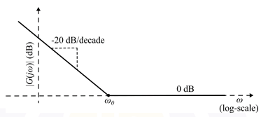
The asymptotic Bode magnitude plot of a system is shown, with a -20 dB/decade slope reaching 0 dB at ω0.
Which one of the following options best represents the transfer function of the system?
Ques 4 GATE 2026
A system is characterized by the following state equation and output equation (u: input, x: state vector, y: output)
ẋ = [[a, b],[−a, 0]]x + [1,0]u
y = [1 2]x
What are the values of a and b for which the poles of the transfer function are at −2 + j3 and −2 − j3?
Ques 5 GATE 2026
A system is represented in state-space form as follows: (u: input, x: state vector, y: output)
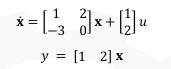
What is the state-space representation of the system in terms of the new state vector z?
Ques 6 GATE 2026
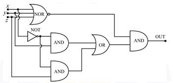
The digital circuit shown has 3 inputs (x, y, and z), involving a NOR gate, NOT gate, AND gates, an OR gate, and a final AND gate.
Ques 7 GATE 2026
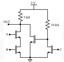
The MOSFET switches shown in the circuit are ideal.
Ques 8 GATE 2026
A 15 kVA, 1100 V/220 V, single-phase two-winding transformer is configured as a 1.32 kV/1.1 kV autotransformer.
What will be the rating of the autotransformer?
Ques 9 GATE 2026
A certain application requires power at a frequency of 16.67 Hz, while the available grid frequency is 50 Hz. A 3-phase synchronous motor connected to the 50 Hz, 3-phase grid, driving a synchronous generator, is used for this application.
Which one of the following combinations is a suitable choice for the number of poles in the motor and generator, respectively?
Ques 10 GATE 2026
Which one of the following options is correct regarding the typical double-squirrel-cage structure used in induction motors?
Ques 11 GATE 2026
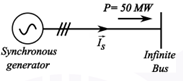
The figure shows the single-line diagram of a synchronous generator delivering P = 50 MW of power at unity power factor to an infinite bus.
Ques 12 GATE 2026
A 220V/12V single-phase transformer is designed for use in India and rated 100 VA at 50 Hz. Later, this unit is shipped to the USA where it is used as a 110V/6V transformer at 60 Hz.
Which of the following statements is/are correct?
Ques 13 GATE 2026
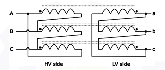
Three single-phase 11kV/3.3kV transformers are connected to form a three-phase transformer bank with connections as shown.
Considering ABC phase sequence, the vector group of the transformer is:

Total Unique Visitors