Electrical Engineering Gate Yearwise
Electrical Gate 2024
Electrical Gate 2023
Electrical Gate 2022
Electrical Gate 2021
Electrical Gate 2020
Electrical Gate 2019
Electrical Gate 2018
Electrical Gate 2017 (Set 1)
Electrical Gate 2017 (Set 2)
Electrical Gate 2016 (Set 1)
Electrical Gate 2016 (Set 2)
Electrical Gate 2015 (Set 1)
Electrical Gate 2015 (Set 2)
Electrical Gate 2014 (Set 1)
Electrical Gate 2014 (Set 2)
Electrical Gate 2014 (Set 3)
Electrical Gate 2013 (Set 1)
Electrical Gate 2013 (Set 2)
Electrical Gate 2013 (Set 3)
Electrical Engineering Gate 2023 Questions with Answer
Ques 53 GATE 2023
A 50 Hz, 275 kV line of length 400 km has the following parameters:
Resistance, R=0.035 Ω/km;
Inductance, L=1 mH/km;
Capacitance, C=0.01 μF/km.
The line is represented by the nominal-π model. With the magnitudes of the sending end and the receiving end voltages of the line (denoted by VS and VR, respectively) maintained at 275 kV, the phase angle difference (δ) between VS and VR required for maximum possible active power to be delivered to the receiving end, in degrees, is _______. (Round off to 2 decimal places).
Ques 54 GATE 2023
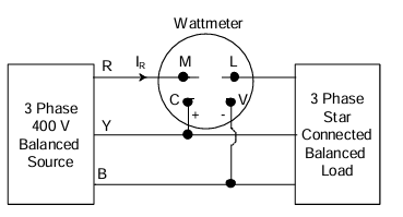
A 3-phase, star-connected, balanced load is supplied from a 3-phase, 400 V (rms), balanced voltage source with phase sequence R-Y-B, as shown in the figure. If the wattmeter reading is -400 W and the line current is IR=2 A (rms), then the power factor of the load per phase is _______.
Ques 55 GATE 2023
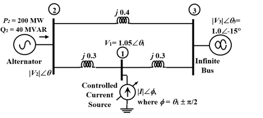
The three-bus power system shown in the figure has one alternator connected to bus 2 which supplies 200 MW and 40 MVAr power. Bus 3 is an infinite bus having a voltage of magnitude |V3|=1.0 p.u. and an angle of -15°. A variable current source, |I|∠φ, is connected at bus 1 and controlled such that the magnitude of the bus 1 voltage is maintained at 1.05 p.u. and the phase angle of the source current, φ=θ1±π/2, where θ1 is the phase angle of the bus 1 voltage. The three buses can be categorized for load flow analysis as _______.
Ques 56 GATE 2023
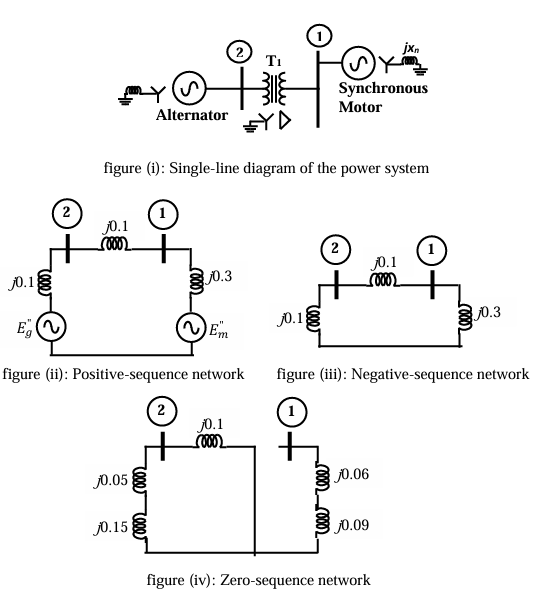
The two-bus power system shown in figure (i) has one alternator supplying a synchronous motor load through a Y-Δ transformer. The positive, negative, and zero-sequence diagrams of the system are shown in figures (ii), (iii), and (iv), respectively. All reactances in the sequence diagrams are in p.u. For a bolted line-to-line fault (fault impedance = zero) between phases 'b' and 'c' at bus 1, neglecting all pre-fault currents, the magnitude of the fault current (from phase 'b' to 'c') in p.u. is _______. (Round off to 2 decimal places).
Ques 57 GATE 2023
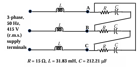
A balanced delta connected load consisting of the series connection of one resistor (R=15 Ω) and a capacitor (C=212.21 μF) in each phase is connected to three-phase, 50 Hz, 415 V supply terminals through a line having an inductance of L=31.83 mH per phase, as shown in the figure. Considering the change in the supply terminal voltage with loading to be negligible, the magnitude of the voltage across the terminals VAB in Volts is _______. (Round off to the nearest integer).
Ques 58 GATE 2023
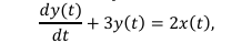
A continuous-time system that is initially at rest is described by
Ques 59 GATE 2023
The Fourier transform X(ω) of the signal x(t) is given by X(ω)=1, for

Ques 60 GATE 2023
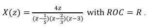
The Z-transform of a discrete signal x[n] is
Ques 61 GATE 2023
Which of the following statement(s) is/are true?
Ques 62 GATE 2023
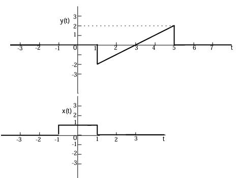
For the signals x(t) and y(t) shown in the figure, z(t)=x(t)y(t) is maximum at t=T1. Then T1 in seconds is _______. (Round off to the nearest integer).
Ques 63 GATE 2023
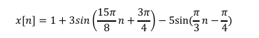
The period of the discrete-time signal x[n] described by the equation
Ques 64 GATE 2023
The discrete-time Fourier transform of a signal x[n] is X(Ω)=(1+cos Ω)e-jΩ. Consider that xp[n] is a periodic signal of period N=5 such that

Ques 65 GATE 2023
A signal x(t)=2cos(180πt)cos(60πt) is sampled at 200 Hz and then passed through an ideal low pass filter having a cut-off frequency of 100 Hz. The maximum frequency present in the filtered signal in Hz is _______. (Round off to the nearest integer).

Total Unique Visitors