Electrical Engineering Gate Yearwise
Electrical Gate 2024
Electrical Gate 2023
Electrical Gate 2022
Electrical Gate 2021
Electrical Gate 2020
Electrical Gate 2019
Electrical Gate 2018
Electrical Gate 2017 (Set 1)
Electrical Gate 2017 (Set 2)
Electrical Gate 2016 (Set 1)
Electrical Gate 2016 (Set 2)
Electrical Gate 2015 (Set 1)
Electrical Gate 2015 (Set 2)
Electrical Gate 2014 (Set 1)
Electrical Gate 2014 (Set 2)
Electrical Gate 2014 (Set 3)
Electrical Gate 2013 (Set 1)
Electrical Gate 2013 (Set 2)
Electrical Gate 2013 (Set 3)
Electrical Engineering Gate 2023 Questions with Answer
Ques 40 GATE 2023
In a given 8-bit general purpose micro-controller there are following flags. W C-Carry, A-Auxiliary Carry, O-Overflow flag, P-Parity (0 for even, 1 for odd) R0 and R1 are the two general purpose registers of the micro-controller. After execution of the following instructions, the decimal equivalent of the binary sequence of the flag pattern [CAOP] will be _______.
MOV R0, +0x60
MOV R1, +0x46
ADD R0, R1
Ques 41 GATE 2023
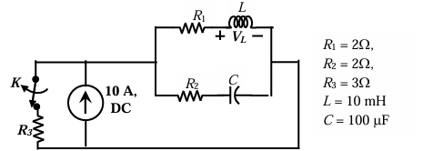
The value of parameters of the circuit shown in the figure are
R1=2 Ω, R2=2 Ω, R3=3 Ω, L=10 mH, C=100 μF.
For time t<0, the circuit is at steady state with the switch 'K' in closed condition. If the switch is opened at t=0, the value of the voltage across the inductor (VL) at t=0+ in Volts is _______. (Round off to 1 decimal place).
Ques 42 GATE 2023
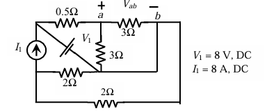
For the circuit shown in the figure, V1=8 V, DC and I1=8 A, DC. The voltage Vab in Volts is _______. (Round off to 1 decimal place).
Ques 43 GATE 2023
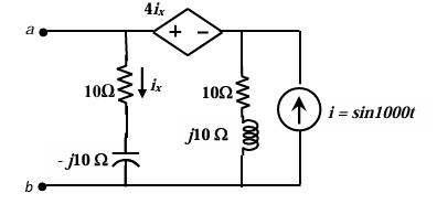
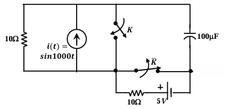
For the circuit shown, if i=sin1000t, the instantaneous value of the Thevenin's equivalent voltage (in Volts) across the terminals a-b at time t=5 ms is _______. (Round off to 2 decimal places).
Ques 44 GATE 2023
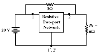
The admittance parameters of the passive resistive two-port network shown in the figure are
y11=5 S, y22=1 S, and y12=y21=-2.5 S.
The power delivered to the load resistor RL in Watt is _______. (Round off to 2 decimal places).
Ques 45 GATE 2023
The circuit shown in the figure is initially in the steady state with the switch K in open condition and K̅ in closed condition. The switch K is closed and K̅ is opened simultaneously at the instant t=t1, where t1>0. The minimum value of t1 in milliseconds, such that there is no transient in the voltage across the 100 μF capacitor, is _______. (Round off to 2 decimal places).
Ques 46 GATE 2023
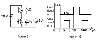
The chopper circuit shown in figure (i) feeds power to a 5 A DC constant current source. The switching frequency of the chopper is 100 kHz. All the components can be assumed to be ideal. The gate signals of switches S1 and S2 are shown in figure (ii). Average voltage across the 5 A current source is _______.
Ques 47 GATE 2023
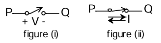
A semiconductor switch needs to block voltage V of only one polarity (V>0) during OFF state as shown in figure (i) and carry current in both directions during ON state as shown in figure (ii). Which of the following switch combination(s) will realize the same?
Ques 48 GATE 2023
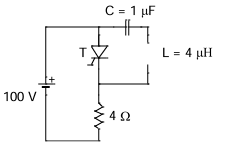
The circuit shown in the figure has reached steady state with thyristor 'T' in OFF condition. Assume that the latching and holding currents of the thyristor are zero. The thyristor is turned ON at t=0 sec. The duration in microseconds for which the thyristor would conduct, before it turns off, is _______. (Round off to 2 decimal places).
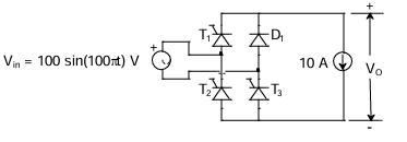
Ques 49 GATE 2023
The single-phase rectifier consisting of three thyristors T1, T2, T3 and a diode D1 feed power to a 10 A constant current load. T1 and T3 are fired at α=60° and T2 is fired at α=240°. The reference for α is the positive zero crossing of Vin. The average voltage Vo across the load in volts is _______. (Round off to 2 decimal places).
Ques 50 GATE 2023
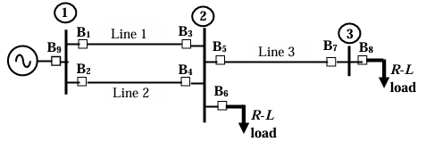
For the three-bus power system shown in the figure, the trip signals to the circuit breakers B1 to B9 are provided by overcurrent relays R1 to R9, respectively, some of which have directional properties also. The necessary condition for the system to be protected for short circuit fault at any part of the system between bus 1 and the R-L loads with isolation of minimum portion of the network using minimum number of directional relays is _______.
Ques 51 GATE 2023
The expressions of fuel cost of two thermal generating units as a function of the respective power generation

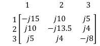
Ques 52 GATE 2023
The bus admittance (Ybus) matrix of a 3-bus power system is given below.

Total Unique Visitors