Electrical Engineering Gate Yearwise
Electrical Gate 2024
Electrical Gate 2023
Electrical Gate 2022
Electrical Gate 2021
Electrical Gate 2020
Electrical Gate 2019
Electrical Gate 2018
Electrical Gate 2017 (Set 1)
Electrical Gate 2017 (Set 2)
Electrical Gate 2016 (Set 1)
Electrical Gate 2016 (Set 2)
Electrical Gate 2015 (Set 1)
Electrical Gate 2015 (Set 2)
Electrical Gate 2014 (Set 1)
Electrical Gate 2014 (Set 2)
Electrical Gate 2014 (Set 3)
Electrical Gate 2013 (Set 1)
Electrical Gate 2013 (Set 2)
Electrical Gate 2013 (Set 3)
Electrical Engineering Gate 2017 Set-2 Questions with Answer
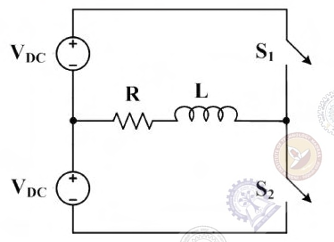
Ques 40 GATE 2017 SET-2
The figure below shows a half-bridge voltage source inverter supplying an RL-load with R=40 Ω and L=(0.3/π)H. The desired fundamental frequency of the load voltage is 50 Hz. The switch control signals of the converter are generated using sinusoidal pulse width modulation with modulation index, M=0.6. At 50 Hz, the RL-load draws an active power of 1.44 kW. The value of DC source voltage VDC in volts is
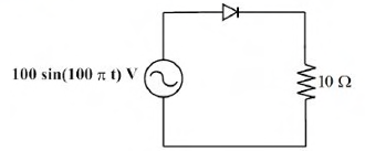
Ques 41 GATE 2017 SET-2
In the circuit shown in the figure, the diode used is ideal. The input power factor is ________. (Give the answer up to two decimal places.)
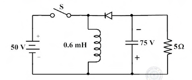
Ques 42 GATE 2017 SET-2
In the circuit shown all elements are ideal and the switch S is operated at 10 kHz and 60% duty ratio. The capacitor is large enough so that the ripple across it is negligible and at steady state acquires a voltage as shown. The peak current in amperes drawn from the 50 V DC source is ________. (Give the answer up to one decimal place.)
Ques 43 GATE 2017 SET-2
A phase-controlled, single-phase, full-bridge converter is supplying a highly inductive DC load. The converter is fed from a 230 V 50 Hz, AC source. The fundamental frequency in Hz of the voltage ripple on the DC side is
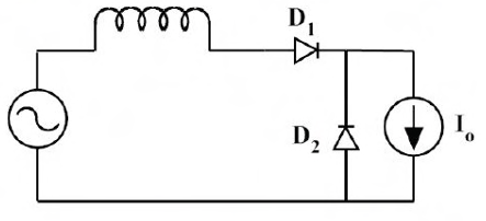
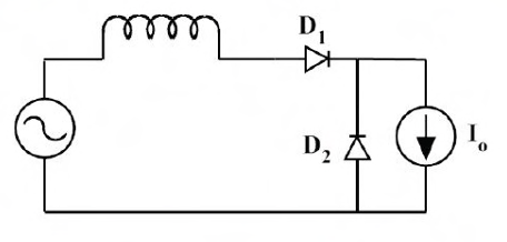
Ques 44 GATE 2017 SET-2
In the circuit shown, the diodes are ideal, the inductance is small, and Io≠0. Which one of the following statements is true?
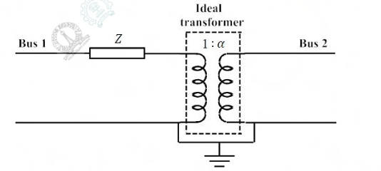
Ques 45 GATE 2017 SET-2
The figure shows the per-phase representation of a phase-shifting transformer connected between buses 1 and 2, where α is a complex number with non-zero real and imaginary parts. For the given circuit, Ybus and Zbus are bus admittance matrix and bus impedance matrix, respectively, each of size 2x2. Which one of the following statements is true?
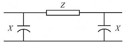
Ques 46 GATE 2017 SET-2
The nominal-π circuit of a transmission line is shown in the figure.
Ques 47 GATE 2017 SET-2
In a load flow problem solved by Newton-Raphson method with polar coordinates, the size of the Jacobian is 100x100. If there are 20 PV buses in addition to PQ buses and a slack bus, the total number of buses in the system is ________.
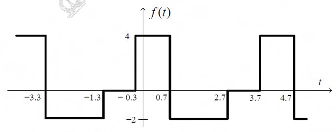
Ques 48 GATE 2017 SET-2
The mean square value of the given periodic waveform f(t) is ________.
Ques 49 GATE 2017 SET-2
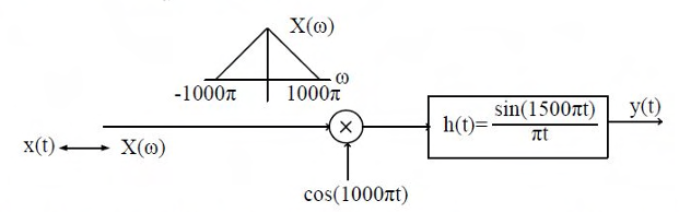
The output y(t) of the following system is to be sampled, so as to reconstruct it from its samples uniquely. The required minimum sampling rate is
Ques 50 GATE 2017 SET-2
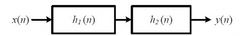
A cascade system having the impulse responses h1(n) = {1, -1} and h2(n) = {1, 1} is shown in the figure below, where symbol ↑ denotes the time origin.

Total Unique Visitors