Electrical Engineering Gate Yearwise
Electrical Gate 2024
Electrical Gate 2023
Electrical Gate 2022
Electrical Gate 2021
Electrical Gate 2020
Electrical Gate 2019
Electrical Gate 2018
Electrical Gate 2017 (Set 1)
Electrical Gate 2017 (Set 2)
Electrical Gate 2016 (Set 1)
Electrical Gate 2016 (Set 2)
Electrical Gate 2015 (Set 1)
Electrical Gate 2015 (Set 2)
Electrical Gate 2014 (Set 1)
Electrical Gate 2014 (Set 2)
Electrical Gate 2014 (Set 3)
Electrical Gate 2013 (Set 1)
Electrical Gate 2013 (Set 2)
Electrical Gate 2013 (Set 3)
Electrical Engineering Gate 2017 Set-2 Questions with Answer
Ques 1 GATE 2017 SET-2
For the circuit shown in the figure below, it is given that VCE = VCC/2. The transistor has β=29 and VBE=0.7 V when the B-E junction is forward biased. For this circuit, the value of RB/R is

Ques 2 GATE 2017 SET-2
For the circuit shown below, assume that the OPAMP is ideal. Which one of the following is TRUE?

Ques 3 GATE 2017 SET-2
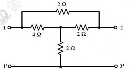
For the given 2-port network, the value of transfer impedance z21 in ohms is ________.
Ques 4 GATE 2017 SET-2
The initial charge in the 1 F capacitor present in the circuit shown is zero. The energy in joules transferred from the DC source until steady state condition is reached equals ________. (Give the answer up to one decimal place.)

Ques 5 GATE 2017 SET-2
For the balanced Y-Y connected 3-phase circuit shown in the figure below, the line-line voltage is 208 V rms and the total power absorbed by the load is 432 W at a power factor of 0.6 leading.

Ques 6 GATE 2017 SET-2
In the circuit shown below, the value of capacitor C required for maximum power to be transferred to the load is

Ques 7 GATE 2017 SET-2
For the network given in figure below, the Thevenin's voltage Vab is

Ques 8 GATE 2017 SET-2
The root locus of the feedback control system having the characteristic equation s2 + 6Ks + 2s + 5 = 0 where K > 0, enters into the real axis at
Ques 9 GATE 2017 SET-2
The range of K for which all the roots of the equation s3 + 3s2 + 2s + K = 0 are in the left half of the complex s-plane is
Ques 10 GATE 2017 SET-2
Which of the following systems has maximum peak overshoot due to a unit step input?
Ques 11 GATE 2017 SET-2
Consider the system described by the following state space representation

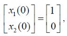 , the value of output y(t) at t=1 sec (rounded off to three decimal places) is ________.
Ques 12 GATE 2017 SET-2
For the synchronous sequential circuit shown below, the output Z is zero for the initial conditions QAQBQC = Q'AQ'BQ'C = 100. The minimum number of clock cycles after which the output Z would again become zero is ________.

Ques 13 GATE 2017 SET-2
A 3-phase, 4-pole, 400 V, 50 Hz squirrel-cage induction motor is operating at a slip of 0.02. The speed of the rotor flux in mechanical rad/sec, sensed by a stationary observer, is closest to

Total Unique Visitors