Electrical Engineering Gate Yearwise
Electrical Gate 2024
Electrical Gate 2023
Electrical Gate 2022
Electrical Gate 2021
Electrical Gate 2020
Electrical Gate 2019
Electrical Gate 2018
Electrical Gate 2017 (Set 1)
Electrical Gate 2017 (Set 2)
Electrical Gate 2016 (Set 1)
Electrical Gate 2016 (Set 2)
Electrical Gate 2015 (Set 1)
Electrical Gate 2015 (Set 2)
Electrical Gate 2014 (Set 1)
Electrical Gate 2014 (Set 2)
Electrical Gate 2014 (Set 3)
Electrical Gate 2013 (Set 1)
Electrical Gate 2013 (Set 2)
Electrical Gate 2013 (Set 3)
Electrical Engineering Gate 2016 Set-1 Questions with Answer
Ques 1 GATE 2016 SET-1
A transistor circuit is given below. The Zener diode breakdown voltage is 5.3 V as shown. Take base to emitter voltage drop to be 0.6 V. The value of the current gain β is ________.
Ques 2 GATE 2016 SET-1
RA and RB are the input resistances of circuits as shown below. The circuits extend infinitely in the direction shown. Which one of the following statements is TRUE?

Ques 3 GATE 2016 SET-1
In the portion of a circuit shown, if the heat generated in 5 Ω resistance is 10 calories per second, then heat generated by the 4 Ω resistance, in calories per second, is ________.

Ques 4 GATE 2016 SET-1
In the given circuit, the current supplied by the battery, in ampere, is ________.
Ques 5 GATE 2016 SET-1
If an ideal transformer has an inductive load element at port 2 as shown in the figure below, the equivalent inductance at port 1 is
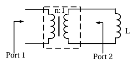
Ques 6 GATE 2016 SET-1
In the circuit shown, switch S2 has been closed for a long time. At time t=0 switch S1 is closed. At t=0+, the rate of change of current through the inductor, in amperes per second, is ________.

Ques 7 GATE 2016 SET-1
In the circuit shown below, the supply voltage is 10 sin(1000t) volts. The peak value of the steady state current through the 1 Ω resistor, in amperes, is ________.

Ques 8 GATE 2016 SET-1
The circuit below is excited by a sinusoidal source. The value of R, in Ω, for which the admittance of the circuit becomes a pure conductance at all frequencies is ________.

Ques 9 GATE 2016 SET-1
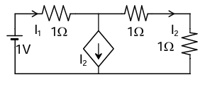
In the circuit shown below, the node voltage VA is ________ V.

Ques 10 GATE 2016 SET-1
The transfer function of a system is Y(s)/R(s) = s/(s+2). The steady state output y(t) is Acos(2t+φ) for the input cos(2t). The values of A and φ, respectively are
Ques 11 GATE 2016 SET-1
The phase cross-over frequency of the transfer function G(s) = 100/(s+1)3 in rad/s is
Ques 12 GATE 2016 SET-1
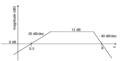
Consider the following asymptotic Bode magnitude plot (ω is in rad/s). Which one of the following transfer functions is best represented by the above Bode magnitude plot?
Ques 13 GATE 2016 SET-1
Consider the following state-space representation of a linear time-invariant system.


Total Unique Visitors