Electrical Engineering Gate Yearwise
Electrical Gate 2024
Electrical Gate 2023
Electrical Gate 2022
Electrical Gate 2021
Electrical Gate 2020
Electrical Gate 2019
Electrical Gate 2018
Electrical Gate 2017 (Set 1)
Electrical Gate 2017 (Set 2)
Electrical Gate 2016 (Set 1)
Electrical Gate 2016 (Set 2)
Electrical Gate 2015 (Set 1)
Electrical Gate 2015 (Set 2)
Electrical Gate 2014 (Set 1)
Electrical Gate 2014 (Set 2)
Electrical Gate 2014 (Set 3)
Electrical Gate 2013 (Set 1)
Electrical Gate 2013 (Set 2)
Electrical Gate 2013 (Set 3)
Electrical Engineering Gate 2015 Set-1 Questions with Answer
Ques 53 GATE 2015 SET-1
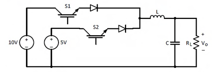
The circuit shown is meant to supply a resistive load RL from two separate DC voltage sources. The switches S1 and S2 are controlled so that only one of them is ON at any instant. S1 is turned on for 0.2 ms and S2 is turned on for 0.3 ms in a 0.5 ms switching cycle time period. Assuming continuous conduction of the inductor current and negligible ripple on the capacitor voltage, the output voltage VO (in Volt) across RL is ________.
Ques 54 GATE 2015 SET-1
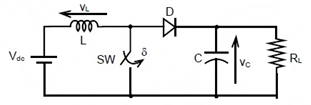
A self commutating switch SW, operated at duty cycle δ is used to control the load voltage as shown in the figure. Under steady state operating conditions, the average voltage across the inductor and the capacitor respectively, are
Ques 55 GATE 2015 SET-1
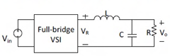
The single-phase full-bridge voltage source inverter (VSI), shown in figure, has an output frequency of 50 Hz. It uses unipolar pulse width modulation with switching frequency of 50 kHz and modulation index of 0.7. For Vin=100 V DC, L=9.55 mH, C=63.66μF, and R=5Ω, the amplitude of the fundamental component in the output voltage V0 (in Volt) under steady-state is ________.
Ques 56 GATE 2015 SET-1
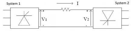
Consider a HVDC link which uses thyristor based line-commutated converters as shown in the figure. For a power flow of 750 MW from System 1 to System 2, the voltages at the two ends, and the current, are given by: V1=500kV, V2=485kV and I=1.5kA. If the direction of power flow is to be reversed (that is, from System 2 to System 1) without changing the electrical connections, then which one of the following combinations is feasible?
Ques 57 GATE 2015 SET-1
Base load power plants are P: wind farms. Q: run-of-river plants. R: nuclear power plants. S: diesel power plants.
Ques 58 GATE 2015 SET-1
Consider the economic dispatch problem for a power plant having two generating units. The fuel costs in Rs/MWh along with the generation limits for the two units are given below:
C1(P1) = 0.01P12 + 30P1 + 10; 100 MW ≤ P1 ≤ 150 MW
C2(P2) = 0.05P22 + 10P2 + 10; 100 MW ≤ P2 ≤ 180 MW
The incremental cost (in Rs/MWh) of the power plant when it supplies 200 MW is ________.
Ques 59 GATE 2015 SET-1
Determine the correctness or otherwise of the following Assertion [a] and the Reason [r].
Assertion: Fast decoupled load flow method gives approximate load flow solution because it uses several assumptions.
Reason: Accuracy depends on the power mismatch vector tolerance.
Ques 60 GATE 2015 SET-1
A 50 Hz generating unit has H-constant of 2 MJ/MVA. The machine is initially operating in steady state at synchronous speed, and producing 1 pu of real power. The initial value of the rotor angle δ is 5°, when a bolted three phase to ground short circuit fault occurs at the terminal of the generator. Assuming the input mechanical power to remain at 1 pu, the value of δ in degrees, 0.02 second after the fault is ________.
Ques 61 GATE 2015 SET-1
A sustained three-phase fault occurs in the power system shown in the figure. The current and voltage phasors during the fault (on a common reference), after the natural transients have died down, are also shown. Where is the fault located?
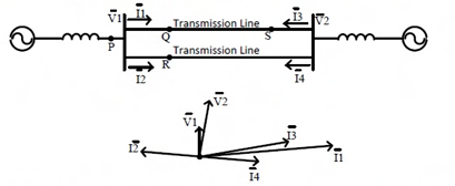
Ques 62 GATE 2015 SET-1
A moving average function is given by y(t) = (1/T)∫t-Tt u(τ)dτ. If the input u is a sinusoidal signal of frequency (1/2T) Hz, then in steady state, the output y will lag u (in degree) by ________.
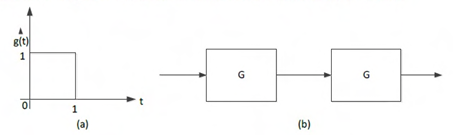
Ques 63 GATE 2015 SET-1
The impulse response g(t) of a system, G, is as shown in Figure (a). What is the maximum value attained by the impulse response of two cascaded blocks of G as shown in Figure (b)?
Ques 64 GATE 2015 SET-1
The signum function is given by
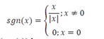
The Fourier series expansion of sgn(cos(t)) has
Ques 65 GATE 2015 SET-1
Consider a discrete time signal given by
x[n] = (-0.25)nu[n] + (0.5)nu[-n-1]. The region of convergence of its Z-transform would be

Total Unique Visitors