Electrical Engineering Gate Yearwise
Electrical Gate 2024
Electrical Gate 2023
Electrical Gate 2022
Electrical Gate 2021
Electrical Gate 2020
Electrical Gate 2019
Electrical Gate 2018
Electrical Gate 2017 (Set 1)
Electrical Gate 2017 (Set 2)
Electrical Gate 2016 (Set 1)
Electrical Gate 2016 (Set 2)
Electrical Gate 2015 (Set 1)
Electrical Gate 2015 (Set 2)
Electrical Gate 2014 (Set 1)
Electrical Gate 2014 (Set 2)
Electrical Gate 2014 (Set 3)
Electrical Gate 2013 (Set 1)
Electrical Gate 2013 (Set 2)
Electrical Gate 2013 (Set 3)
Electrical Engineering Gate 2013 Set-1 Questions with Answer
Ques 14 GATE 2013 SET-1
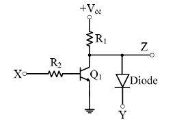
In the circuit shown below, Q1 has negligible collector-to-emitter saturation voltage and the diode drops negligible voltage across it under forward bias. If V<sub>cc</sub> is +5 V, X and Y are digital signals with 0 V as logic 0 and Vcc as logic 1, then the Boolean expression for Z is
Ques 15 GATE 2013 SET-1
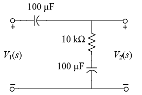
The transfer function V2(s)/V1(s) of the circuit shown below is
Ques 16 GATE 2013 SET-1
A source vs(t) = 100 cos(πt) V has an internal impedance of (4 + j3) Ω. If a purely resistive load is connected to extract maximum power, its value in Ω should be?
Ques 17 GATE 2013 SET-1
A single-phase voltage source supplies a load. If the current is 10∠−150° A and voltage is 100∠60° V, then the load
Ques 18 GATE 2013 SET-1
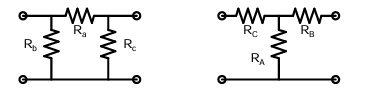
Consider a delta connection of resistors and its equivalent star connection as shown below. If all elements of the delta connection are scaled by a factor k, k > 0, the elements of the corresponding star equivalent will be scaled by a factor of
Ques 19 GATE 2013 SET-1
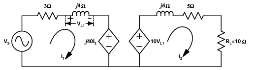
For the given AC circuit, source voltage Vs = 100∠53.13° V. Find the Thevenin's equivalent voltage as seen by RL.
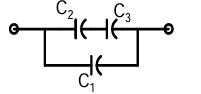
Ques 20 GATE 2013 SET-1
Three capacitors C1, C2, and C3, whose values are 10µF, 5µF, and 2µF respectively, have breakdown voltages of 10V, 5V, and 2V respectively. For the interconnection shown, the maximum safe voltage in Volts that can be applied across the combination and the corresponding total charge in µC stored in the effective capacitance across the terminals are respectively
Ques 21 GATE 2013 SET-1
Two magnetically uncoupled inductive coils have Q factors q1 and q2 at the chosen operating frequency. Their respective resistances are R1 and R2. When connected in series, their effective Q factor at the same operating frequency is
Ques 22 GATE 2013 SET-1
A single-phase transformer has no-load loss of 64 W. With 90% of rated current during a short-circuit test, the measured loss is 81 W. The transformer has maximum efficiency when operated at
Ques 23 GATE 2013 SET-1
The angle δ in the swing equation of a synchronous generator is the
Ques 24 GATE 2013 SET-1
Leakage flux in an induction motor is
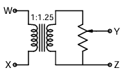
Ques 25 GATE 2013 SET-1
The following arrangement consists of an ideal transformer and an attenuator which attenuates by a factor of 0.8. An ac voltage VWX1 = 100V is applied across WX to get an open circuit voltage VYZ1 across YZ. Next, an ac voltage VYZ2 = 100V is applied across YZ to get an open circuit voltage VWX2 across WX. Then, VYZ1 / VWX1 , VWX2 / VYZ2 are respectively,
Ques 26 GATE 2013 SET-1
A 4-pole induction motor, supplied by a slightly unbalanced three-phase 50 Hz source, is rotating at 1440 rpm. The electrical frequency in Hz of the induced negative sequence current in the rotor is

Total Unique Visitors