Electrical Engineering Gate Yearwise
Electrical Gate 2024
Electrical Gate 2023
Electrical Gate 2022
Electrical Gate 2021
Electrical Gate 2020
Electrical Gate 2019
Electrical Gate 2018
Electrical Gate 2017 (Set 1)
Electrical Gate 2017 (Set 2)
Electrical Gate 2016 (Set 1)
Electrical Gate 2016 (Set 2)
Electrical Gate 2015 (Set 1)
Electrical Gate 2015 (Set 2)
Electrical Gate 2014 (Set 1)
Electrical Gate 2014 (Set 2)
Electrical Gate 2014 (Set 3)
Electrical Gate 2013 (Set 1)
Electrical Gate 2013 (Set 2)
Electrical Gate 2013 (Set 3)
Electrical Engineering Gate 2024 Questions with Answer
Ques 40 GATE 2024
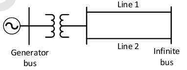
The single line diagram of a lossless system is shown in the figure. The system is operating in steady-state at a stable equilibrium point with the power output of the generator being Pmax sin δ, where δ is the load angle and the mechanical power input is 0.5Pmax. A fault occurs on line 2 such that the power output of the generator is less than 0.5Pmax during the fault. After the fault is cleared by opening line 2, the power output of the generator is (Pmax/√2) sin δ. If the critical fault clearing angle is π/2 radians, the accelerating area on the power angle curve is _______ times Pmax. (rounded off to 2 decimal places)
Ques 41 GATE 2024
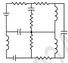
The number of junctions in the circuit is _______.
Ques 42 GATE 2024
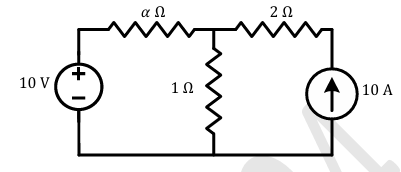
All the elements in the circuit are ideal. The power delivered by the 10 V source in watts is _______.
Ques 43 GATE 2024
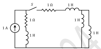
The circuit shown in the figure with the switch S open is in steady state. After the switch S is closed, the time constant of the circuit in seconds is _______.
Ques 44 GATE 2024
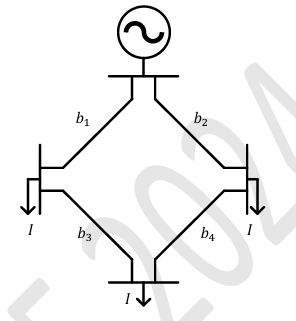
The figure shows the single line diagram of a 4-bus power network. Branches b1, b2, b3, and b4 have impedances 4z, z, 2z, and 4z per-unit (pu), respectively, where z=r+jx with r>0 and x>0. The current drawn from each load bus (marked as arrows) is equal to I pu, where I≠0. If the network is to operate with minimum loss, the branch that should be opened is _______.
Ques 45 GATE 2024
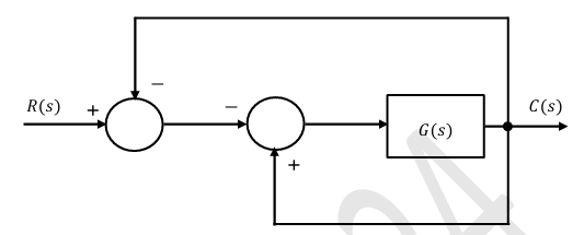
For the block-diagram shown in the figure, the transfer function C(s)/R(s) is _______.
Ques 46 GATE 2024
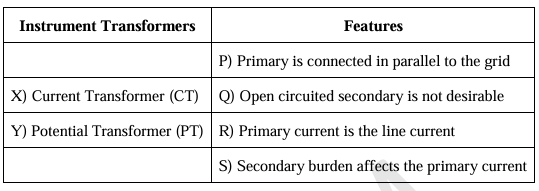
The table lists two instrument transformers and their features: Instrument Transformers Features P) Primary is connected in parallel to the grid X) Current Transformer (CT) Q) Open circuited secondary is not desirable Y) Potential Transformer (PT) R) Primary current is the line current S) Secondary burden affects the primary current.
Ques 47 GATE 2024
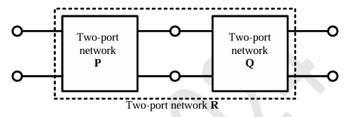
Two passive two-port networks P and Q are connected as shown in the figure. The impedance matrix of network P is Zp=[[40 Ω,60 Ω],[80 Ω,100 Ω]].
The admittance matrix of network Q is YQ=[[5 S,-2.5 S],[-2.5 S,1 S]]. Let the ABCD matrix of the two-port network R in the figure be [[α,β],[γ,δ]].
The value of α in Ω is _______. (rounded off to 2 decimal places)
Ques 48 GATE 2024
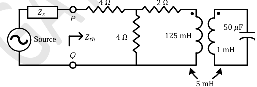
For the circuit shown in the figure, the source frequency is 5000 rad/sec. The mutual inductance between the magnetically coupled inductors is 5 mH with their self inductances being 125 mH and 1 mH. The Thevenin's impedance, Zth, between the terminals P and Q in Ω is _______. (rounded off to 2 decimal places)
Ques 49 GATE 2024
If the following switching devices have similar power ratings, which one of them is the fastest?
Ques 50 GATE 2024
A single-phase triac based AC voltage controller feeds a series RL load. The AC supply is 230 V, 50 Hz. The values of R and L are 10 Ω and 18.37 mH, respectively. The minimum triggering angle of the triac to obtain controllable output voltage is _______.
Ques 51 GATE 2024
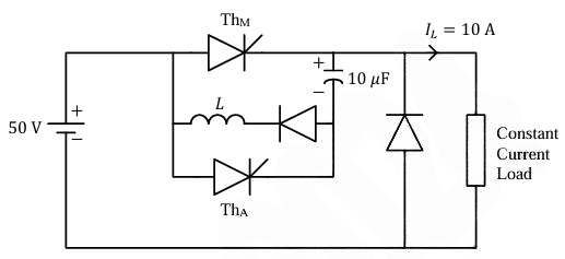
A forced commutated thyristorized step-down chopper is shown in the figure. Neglect the ON-state drop across the power devices. Assume that the capacitor is initially charged to 50 V with the polarity shown in the figure. The load current (IL) can be assumed to be constant at 10 A. Initially, Th is ON and ThA is OFF. The turn-off time available to The in microseconds, when ThA is triggered, is _______. (rounded off to the nearest integer)
Ques 52 GATE 2024
A single-phase half-controlled bridge converter supplies an inductive load with ripple free load current. The triggering angle of the converter is 60°. The ratio of the rms value of the fundamental component of the input current to the rms value of the total input current of the bridge is _______. (rounded off to 3 decimal places)

Total Unique Visitors