Electrical Engineering Gate Yearwise
Electrical Gate 2024
Electrical Gate 2023
Electrical Gate 2022
Electrical Gate 2021
Electrical Gate 2020
Electrical Gate 2019
Electrical Gate 2018
Electrical Gate 2017 (Set 1)
Electrical Gate 2017 (Set 2)
Electrical Gate 2016 (Set 1)
Electrical Gate 2016 (Set 2)
Electrical Gate 2015 (Set 1)
Electrical Gate 2015 (Set 2)
Electrical Gate 2014 (Set 1)
Electrical Gate 2014 (Set 2)
Electrical Gate 2014 (Set 3)
Electrical Gate 2013 (Set 1)
Electrical Gate 2013 (Set 2)
Electrical Gate 2013 (Set 3)
Electrical Engineering Gate 2014 Set-3 Questions with Answer
Ques 1 GATE 2014 SET-3
An operational-amplifier circuit is shown in the figure.

Ques 2 GATE 2014 SET-3
The signal flow graph of a system is shown below. U(s) is the input and C(s) is the output.

Ques 3 GATE 2014 SET-3
A single-input single-output feedback system has forward transfer function G(s) and feedback transfer function H(s). It is given that |G(s)H(s)|<1. Which of the following is true about the stability of the system?
Ques 4 GATE 2014 SET-3
A state diagram of a logic gate which exhibits a delay in the output is shown in the figure, where X is the don't care condition, and Q is the output representing the state.

Ques 5 GATE 2014 SET-3
The line A to neutral voltage is 10∠15°V for a balanced three phase star-connected load with phase sequence ABC. The voltage of line B with respect to line C is given by
Ques 6 GATE 2014 SET-3
The driving point impedance Z(s) for the circuit shown below is

Ques 7 GATE 2014 SET-3
A non-ideal voltage source VS has an internal impedance of ZS. If a purely resistive load is to be chosen that maximizes the power transferred to the load, its value must be
Ques 8 GATE 2014 SET-3
The Norton's equivalent source in amperes as seen into the terminals X and Y is ________.

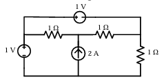
Ques 9 GATE 2014 SET-3
The power supplied by the 2A current source, in the figure, is ________ W.
Ques 10 GATE 2014 SET-3
A series RLC circuit is observed at two frequencies. At ω1=1 krad/s, we note that source voltage V1=100∠0° V results in a current I1=0.03∠31° A. At ω2=2 krad/s, the source voltage V2=100∠0° V results in a current I2=2∠0° A. The closest values for R, L, C out of the following options are
Ques 11 GATE 2014 SET-3
In a synchronous machine, hunting is predominantly damped by
Ques 12 GATE 2014 SET-3
A single phase induction motor is provided with capacitor and centrifugal switch in series with auxiliary winding. The switch is expected to operate at a speed of 0.7 Ns, but due to malfunctioning the switch fails to operate. The torque-speed characteristic of the motor is represented by
Ques 13 GATE 2014 SET-3
The no-load speed of a 230 V separately excited dc motor is 1400 rpm. The armature resistance drop and the brush drop are neglected. The field current is kept constant at rated value. The torque of the motor in Nm for an armature current of 8 A is ________.

Total Unique Visitors