Electrical Engineering > GATE 2026 > Electromagnetic Induction
The figure shows an arbitrarily shaped planar conducting loop A in the XY plane. Two nonintersecting regions with areas a1 and a2 within the loop are subjected to magnetic fields B⃗1 = (m/√2)sin(ωt)(1x̂+0ŷ+1ẑ), and B⃗2 = −(n/√2)cos(2ωt+π/4)(0x̂+1ŷ+1ẑ), respectively.
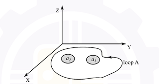 What is the expression for the induced rms voltage in loop A?
Correct : a
Similar Questions
A rotating conductor of 1 m length is placed in a radially outward (about the z-axis) magnetic flux density (B) of 1 Tesla as shown in figure below. Conductor i...
Consider a one-turn rectangular loop of wire placed in a uniform magnetic field as shown in the figure. The plane of the loop is perpendicular to the field line...
A circular turn of radius 1 m revolves at 60 rpm about its diameter aligned with the x-axis as shown in the figure. The value of μ0 is 4πx10-7 in SI unit. If a...

Total Unique Visitors
Loading......