Electrical Engineering > GATE 2026 > DC-DC Converters
Consider the boost converter circuit shown. Assume that the semiconductor devices are ideal. In steady state, the inductor current rises linearly from 0 A to 6 A in the first 10 µs and then falls linearly from 6 A to 0 A in the next 10 µs of every switching cycle as shown. The load resistance R is 10 Ω and the capacitance C is 500 µF.
Neglect the ripple in the output voltage. What is the input voltage Vdc?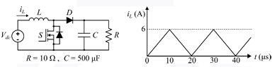
Neglect the ripple in the output voltage. What is the input voltage Vdc?
Correct : b
Similar Questions
In the DC-DC converter shown in the figure, the current through the inductor is continuous. The switching frequency is 500 Hz. The voltage (Vo) across the load...
Consider the buck-boost converter shown. Switch Q is operating at 25 kHz and 0.75 duty-cycle. Assume diode and switch to be ideal. Under steady-state condition,...
In the dc-dc converter circuit shown, switch Q is switched at a frequency of 10 kHz with a duty ratio of 0.6. All components of the circuit are ideal, and the i...

Total Unique Visitors
Loading......