Electrical Engineering > GATE 2026 > Voltage Source Inverters
Consider the single-phase voltage source inverter circuit feeding an inductive load (L). Assume that the power MOSFET switches are ideal. S1 and S2 are switched on during the first 10 µs, and S3 and S4 are switched on during the next 10 µs in a switching cycle. The switches in the same leg are thus switched in a complementary fashion. Neglect the dead time. The waveform of the inductor current (iL) in the steady state is triangular with a peak value of 5 A as shown.
The rms value of the current through the switch S1 is: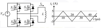
The rms value of the current through the switch S1 is:
Correct : b
Similar Questions
A 3-phase voltage source inverter is supplied from a 600V DC source as shown in the figure below. For a star connected resistive load of 202 per phase, the load...
As you grow older, an injury to your _________ may take longer to _________.
In a 500 m race, P and Q have speeds in the ratio of 3 ∶ 4. Q starts the race when P has already covered 140 m.
What is the distance between P and Q (in m) whe...

Total Unique Visitors
Loading......