Electrical Engineering > GATE 2024 > AC Circuits
For the circuit shown in the figure, the source frequency is 5000 rad/sec. The mutual inductance between the magnetically coupled inductors is 5 mH with their self inductances being 125 mH and 1 mH. The Thevenin's impedance, Zth, between the terminals P and Q in Ω is _______. (rounded off to 2 decimal places)
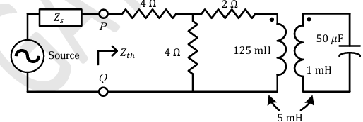
Correct : 4.00
Similar Questions
Currents through ammeters A2 and A3 in the figure are 1∠10° and 1∠70°, respectively. The reading of the ammeter A1(rounded off to 3 decimal places) is ________...
A three-phase balanced voltage is applied to the load shown. The phase sequence is RYB. The ratio \\frac{|IB|}{|IR|} is
In the circuit shown below, the value of capacitor C required for maximum power to be transferred to the load is

Total Unique Visitors
Loading......