Electrical Engineering > GATE 2024 > Power System Analysis
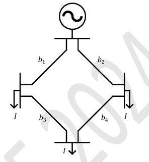
The figure shows the single line diagram of a 4-bus power network. Branches b1, b2, b3, and b4 have impedances 4z, z, 2z, and 4z per-unit (pu), respectively, where z=r+jx with r>0 and x>0. The current drawn from each load bus (marked as arrows) is equal to I pu, where I≠0. If the network is to operate with minimum loss, the branch that should be opened is _______.
Correct : d
Similar Questions
A 3-Bus network is shown. Consider generators as ideal voltage sources. If rows 1, 2 and 3 of the YBus matrix correspond to Bus 1, 2 and 3, respectively, then Y...
The figure shows the per-phase representation of a phase-shifting transformer connected between buses 1 and 2, where α is a complex number with non-zero real an...
In the following network, the voltage magnitudes at all buses are equal to 1 p.u., the voltage phase angles
are very small, and the line resistances are negli...

Total Unique Visitors
Loading......