Electrical Engineering > GATE 2023 > Fault Analysis
The two-bus power system shown in figure (i) has one alternator supplying a synchronous motor load through a Y-Δ transformer. The positive, negative, and zero-sequence diagrams of the system are shown in figures (ii), (iii), and (iv), respectively. All reactances in the sequence diagrams are in p.u. For a bolted line-to-line fault (fault impedance = zero) between phases 'b' and 'c' at bus 1, neglecting all pre-fault currents, the magnitude of the fault current (from phase 'b' to 'c') in p.u. is _______. (Round off to 2 decimal places).
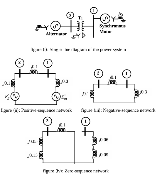
Correct : 3.09
Similar Questions
Five alternators each rated 5 MVA, 13.2 kV with 25% of reactance on its own base are connected in parallel to a
busbar. The short-circuit level in MVA at the b...
The positive, negative and zero sequence impedances of a 125 MVA, three-phase, 15.5 kV, star-grounded, 50 Hz generator are j0.1 pu, j0.05 pu and j0.01 pu respec...
The positive, negative and zero sequence impedances of a three phase generator are Z1, Z2, and Z0 respectively. For a line-to-line fault with fault impedance Zf...

Total Unique Visitors
Loading......