Electrical Engineering > GATE 2023 > Load Flow Analysis
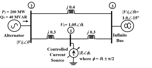
The three-bus power system shown in the figure has one alternator connected to bus 2 which supplies 200 MW and 40 MVAr power. Bus 3 is an infinite bus having a voltage of magnitude |V3|=1.0 p.u. and an angle of -15°. A variable current source, |I|∠φ, is connected at bus 1 and controlled such that the magnitude of the bus 1 voltage is maintained at 1.05 p.u. and the phase angle of the source current, φ=θ1±π/2, where θ1 is the phase angle of the bus 1 voltage. The three buses can be categorized for load flow analysis as _______.
Correct : d
Similar Questions
Consider a power system consisting of N number of buses. Buses in this power system are categorized into slack bus, PV buses and PQ buses for load flow study. T...
Out of the following options, the most relevant information needed to specify the real power (P) at the PV buses in a load flow analysis is
A 10-bus power system consists of four generator buses indexed as G1, G2, G3, G4 and six load buses indexed as L1, L2, L3, L4, L5, L6. The generator-bus G1 is c...

Total Unique Visitors
Loading......