Electrical Engineering > GATE 2023 > RLC Circuits
The value of parameters of the circuit shown in the figure are
R1=2 Ω, R2=2 Ω, R3=3 Ω, L=10 mH, C=100 μF.
For time t<0, the circuit is at steady state with the switch 'K' in closed condition. If the switch is opened at t=0, the value of the voltage across the inductor (VL) at t=0+ in Volts is _______. (Round off to 1 decimal place).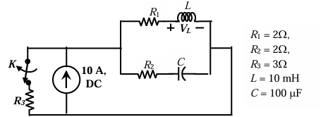
R1=2 Ω, R2=2 Ω, R3=3 Ω, L=10 mH, C=100 μF.
For time t<0, the circuit is at steady state with the switch 'K' in closed condition. If the switch is opened at t=0, the value of the voltage across the inductor (VL) at t=0+ in Volts is _______. (Round off to 1 decimal place).
Correct : 30.0
Similar Questions
As you grow older, an injury to your _________ may take longer to _________.
In a 500 m race, P and Q have speeds in the ratio of 3 ∶ 4. Q starts the race when P has already covered 140 m.
What is the distance between P and Q (in m) whe...
Three bells P, Q, and R are rung periodically in a school. P is rung every 20 minutes; Q is rung every 30 minutes and R is rung every 50 minutes. If all the thr...

Total Unique Visitors
Loading......