Electrical Engineering > GATE 2023 > Choppers
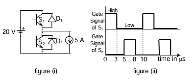
The chopper circuit shown in figure (i) feeds power to a 5 A DC constant current source. The switching frequency of the chopper is 100 kHz. All the components can be assumed to be ideal. The gate signals of switches S1 and S2 are shown in figure (ii). Average voltage across the 5 A current source is _______.
Correct : a
Similar Questions
A forced commutated thyristorized step-down chopper is shown in the figure. Neglect the ON-state drop across the power devices. Assume that the capacitor is ini...
As you grow older, an injury to your _________ may take longer to _________.
In a 500 m race, P and Q have speeds in the ratio of 3 ∶ 4. Q starts the race when P has already covered 140 m.
What is the distance between P and Q (in m) whe...

Total Unique Visitors
Loading......