Electrical Engineering > GATE 2022 > Time Domain Analysis
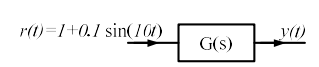
An LTI system is shown in the figure where G(s) = 100/(s2+0.1s+100). The steady state output of the system, to the input r(t) = 1 + 0.1sin(10t), is given as y(t) = a + b sin(10t+θ). The values of 'a' and 'b' will be
Correct : a
Similar Questions
The damping ratio and undamped natural frequency of a closed loop system as shown in the figure, are denoted as ζ and ωn, respectively. The values of ζ and ωn a...
Which of the following systems has maximum peak overshoot due to a unit step input?
A second-order real system has the following properties:a) the damping ratio ζ = 0.5 and undamped natural frequency ωn = 10 rad/s,b) the steady state value of t...

Total Unique Visitors
Loading......