Electrical Engineering > GATE 2018 > Induction Motors
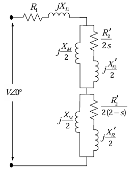
The equivalent circuit of a single phase induction motor is shown in the figure, where the parameters are Xl1 = Xl2 = 2 Ω, R1 = R2 = 2 Ω, XM = 240 Ω and s is the slip. [cite: 115] At no-load, the motor speed can be approximated to be the synchronous speed. [cite: 116, 117] The no-load lagging power factor of the motor is___________ (up to 3 decimal places).
Correct : 0.105
Similar Questions
A three-phase, 50 Hz, 6 pole induction motor runs at 960 rpm. The stator copper loss, core loss, and the rotational loss of the motor can be neglected. The perc...
A 3-phase star connected slip ring induction motor has the following parameters referred to the stator: Rs=3 Ω, Xs=2 Ω, Xr'=2 Ω, Rr'=2.5 Ω. The per phase stator...
The following columns present various modes of induction machine operation and the ranges of slip:
The correct matching between the elements in column A wi...

Total Unique Visitors
Loading......