Electrical Engineering > GATE 2018 > DC-DC Converters
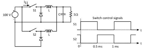
The figure shows two buck converters connected in parallel. The common input dc voltage for the converters has a value of 100 V. The converters have inductors of identical value. The load resistance is 1 Ω. The capacitor voltage has negligible ripple. Both converters operate in the continuous conduction mode. The switching frequency is 1 kHz, and the switch control signals are as shown. The circuit operates in the steady state. Assuming that the converters share the load equally, the average value of iS1, the current of switch S1 (in Ampere), is _____ (up to 2 decimal places).
 Parallel">
Correct : 12.50
Similar Questions
In the DC-DC converter shown in the figure, the current through the inductor is continuous. The switching frequency is 500 Hz. The voltage (Vo) across the load...
Consider the buck-boost converter shown. Switch Q is operating at 25 kHz and 0.75 duty-cycle. Assume diode and switch to be ideal. Under steady-state condition,...
In the dc-dc converter circuit shown, switch Q is switched at a frequency of 10 kHz with a duty ratio of 0.6. All components of the circuit are ideal, and the i...

Total Unique Visitors
Loading......