Electrical Engineering > Gate 2018 > Load flow
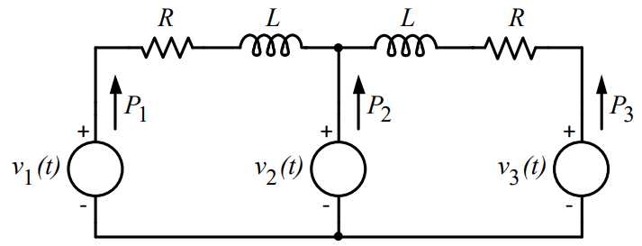
In the figure, the voltages are 𝑣1(𝑡) = 100cos(𝜔𝑡), 𝑣2(𝑡) = 100cos(𝜔𝑡 + 𝜋/18) and
𝑣3(𝑡) = 100cos(𝜔𝑡 + 𝜋/36). The circuit is in sinusoidal steady state, and 𝑅 << 𝜔𝐿. 𝑃1,
𝑃2 and 𝑃3 are the average power outputs. Which one of the following statements is true?
Correct : c
Similar Questions
Two generating units rated for 250 MW and 400 MW have governor speed regulations of 6% and 6.4%, respectively, from no load to full load. Both the generating un...
In a load flow problem solved by Newton-Raphson method with polar coordinates, the size of the Jacobian is 100x100. If there are 20 PV buses in addition to PQ b...
In a 100 bus power system, there are 10 generators. In a particular iteration of Newton Raphson load flow technique (in polar coordinates), two of the PV buses...

Total Unique Visitors
Loading......