Electrical Engineering > GATE 2017 SET-2 > Rectifiers
In the circuit shown in the figure, the diode used is ideal. The input power factor is ________. (Give the answer up to two decimal places.)
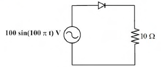
Correct : 0.707
Similar Questions
The single-phase rectifier consisting of three thyristors T1, T2, T3 and a diode D1 feed power to a 10 A constant current load. T1 and T3 are fired at α=60° and...
In the circuit shown, the input Vi is a sinusoidal AC voltage having an RMS value of 230V ± 20%. The worst-case peak-inverse voltage seen across any diode is __...
A single-phase, full-bridge diode rectifier fed from a 230 V, 50 Hz sinusoidal source supplies a series combination of finite resistance, R, and a very large in...

Total Unique Visitors
Loading......