Electrical Engineering > GATE 2016 SET-2 > Stability
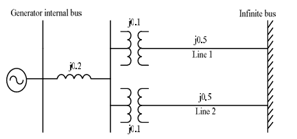
The single line diagram of a balanced power system is shown in the figure. The voltage magnitude at the generator internal bus is constant and 1.0 p.u. The p.u. reactances of different components in the system are also shown in the figure. The infinite bus voltage magnitude is 1.0 p.u. A three phase fault occurs at the middle of line 2. The ratio of the maximum real power that can be transferred during the pre-fault condition to the maximum real power that can be transferred under the faulted condition is ________.
Correct : 2.33
Similar Questions
A 20 MVA, 11.2 kV, 4-pole, 50 Hz alternator has an inertia constant of 15 MJ/MVA. If the input and output powers of the alternator are 15 MW and 10 MW, respecti...
A 50 Hz generating unit has H-constant of 2 MJ/MVA. The machine is initially operating in steady state at synchronous speed, and producing 1 pu of real power. T...
The synchronous generator shown in the figure is supplying active power to an infinite bus via two short, lossless transmission lines, and is initially in stead...

Total Unique Visitors
Loading......