Electrical Engineering > GATE 2016 SET-1 > Inverters
The switches T1 and T2 in Figure (a) are switched in a complementary fashion with sinusoidal pulse width modulation technique. The modulating voltage vm(t) = 0.8sin(200πt) V and the triangular carrier voltage (vc) are as shown in Figure (b). The carrier frequency is 5 kHz. The peak value of the 100 Hz component of the load current (iL), in ampere, is ________.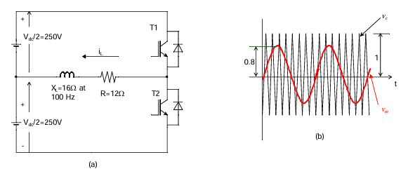
Correct : 10
Similar Questions
A single-phase full bridge voltage source inverter (VSI) feeds a purely inductive load. The inverter output voltage is a square wave in 180° conduction mode. Th...
A single-phase full-bridge inverter fed by a 325 V DC produces a symmetric quasi-square waveform across 'ab' as shown. To achieve a modulation index of 0.8, the...
A single-phase inverter is fed from a 100 V de source and is controlled using a quasi-square wave modulation scheme to produce an output waveform, v(t), as show...

Total Unique Visitors
Loading......