Electrical Engineering > GATE 2016 SET-1 > DC-DC Converters
A buck converter, as shown in Figure (a) below, is working in steady state. The output voltage and the inductor current can be assumed to be ripple free. Figure (b) shows the inductor voltage VL during a complete switching interval. Assuming all devices are ideal, the duty cycle of the buck converter is ________.
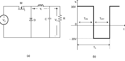
Correct : 0.4
Similar Questions
In the DC-DC converter shown in the figure, the current through the inductor is continuous. The switching frequency is 500 Hz. The voltage (Vo) across the load...
Consider the buck-boost converter shown. Switch Q is operating at 25 kHz and 0.75 duty-cycle. Assume diode and switch to be ideal. Under steady-state condition,...
In the dc-dc converter circuit shown, switch Q is switched at a frequency of 10 kHz with a duty ratio of 0.6. All components of the circuit are ideal, and the i...

Total Unique Visitors
Loading......