Electrical Engineering > GATE 2015 SET-1 > DC-DC Converters
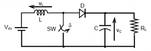
A self commutating switch SW, operated at duty cycle δ is used to control the load voltage as shown in the figure. Under steady state operating conditions, the average voltage across the inductor and the capacitor respectively, are
Correct : a
Similar Questions
In the DC-DC converter shown in the figure, the current through the inductor is continuous. The switching frequency is 500 Hz. The voltage (Vo) across the load...
Consider the buck-boost converter shown. Switch Q is operating at 25 kHz and 0.75 duty-cycle. Assume diode and switch to be ideal. Under steady-state condition,...
In the dc-dc converter circuit shown, switch Q is switched at a frequency of 10 kHz with a duty ratio of 0.6. All components of the circuit are ideal, and the i...

Total Unique Visitors
Loading......