Electrical Engineering > GATE 2013 SET-1 > Inverters
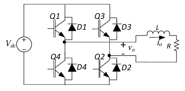
The Voltage Source Inverter (VSI) shown in the figure below is switched to provide a 50 Hz, square-wave ac output voltage (vo) across an R-L load. Reference polarity of vo and reference direction of the output current io are indicated in the figure. It is given that R = 3 Ω, L=9.55 mH.
 Appropriate transition i.e., Zero Voltage Switching (ZVS)/Zero Current Switching (ZCS) of the IGBTs during turn-on/turn-off is
Correct :
Similar Questions
A single-phase full bridge voltage source inverter (VSI) feeds a purely inductive load. The inverter output voltage is a square wave in 180° conduction mode. Th...
A single-phase full-bridge inverter fed by a 325 V DC produces a symmetric quasi-square waveform across 'ab' as shown. To achieve a modulation index of 0.8, the...
A single-phase inverter is fed from a 100 V de source and is controlled using a quasi-square wave modulation scheme to produce an output waveform, v(t), as show...

Total Unique Visitors
Loading......