EC > GATE 2025 > Network Analysis
Consider a part of an electrical network as shown below. Some node voltages, and the current flowing through the 3Ω resistor are as indicated.
The voltage (in Volts) at node X is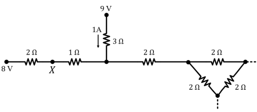
The voltage (in Volts) at node X is
Correct : b
Similar Questions
The current I in the circuit shown is ________.
Consider the circuit shown in the figure. The current I flowing through the 10 Ω resistor is _______
For the circuit shown, the locus of the impedance Z(jω) is plotted as ω increases from zero to infinity. The values of R1 and R2 are:

Total Unique Visitors
Loading......