EC > GATE 2023 > Block Diagram Reduction
In the following block diagram, R(s) and D(s) are two inputs. The output Y(s) is expressed as Y(s) = G1(s)R(s) + G2(s)D(s). G1(s) and G2(s) are given by
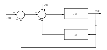
A
G1(s) = G(s)/1 + G(s) + G(s)H(s) and G2(s) = G(s)/1 + G(s) + G(s)H(s)
B
G1(s) = G(s)/1 + G(s) + H(s) and G2(s) = G(s)/1 + G(s) + H(s)
C
G1(s) = G(s)/1 + G(s) + H(s) and G2(s) = G(s)/1 + G(s) + G(s)H(s)
D
G1(s) = G(s)/1 + G(s) + G(s)H(s) and G2(s) = G(s)/1 + G(s) + H(s)

Correct : a

Similar Questions

The block diagram of a system is illustrated in the figure shown, where X(s) is the input and Y(s) is the output. The transfer function H(s)=Y(s)/X(s) is
#381 MCQ
For the system shown in the figure, Y(s)/X(s)=
#552 Fill in the Blanks
Mr. X speaks _________ Japanese _________ Chinese.

#3 MCQ

Related Topics

block diagram analysis GATE EC 2023 feedback control systems transfer function G(s) H(s) in block diagram G1(s) G2(s) in block diagram feedback control systems GATE system block diagram analysis

Unique Visitor Count

Total Unique Visitors

Loading......