EC > GATE 2023 > Diode Circuits
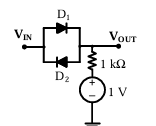
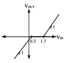
In the circuit shown below, D1 and D2 are silicon diodes with cut-in voltage of 0.7 V. VIN and VOUT are input and output voltages in volts. The transfer characteristic is
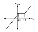
A
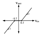
B
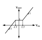
C
D
Correct : a
Similar Questions
In the circuit shown, the n: 1 step-down transformer and the diodes are ideal.The diodes have no voltage drop in forward biased condition.If the input voltage (...
All the diodes in the circuit given below are ideal.Which of the following plots is/are correct when VI (in Volts) is swept from -M to M?
The diode in the circuit shown below is ideal. The input voltage (in Volts) is given by VI=10 sin 100πt, where time t is in seconds.The time duration (in ms,...

Total Unique Visitors
Loading......