EC > GATE 2023 > Op-amp Circuits
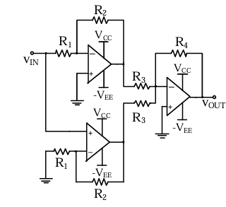
The VOUT/VIN of the circuit shown below is
Correct : a
Similar Questions
An ideal OPAMP circuit with a sinusoidal input is shown in the figure. The 3 dB frequency is the frequency at which the magnitude of the voltage gain decreases...
For the following circuit with an ideal OPAMP, the difference between the maximum and the minimum values of the capacitor voltage (VC) is __________.
A circuit with an ideal OPAMP is shown. The Bode plot for the magnitude (in dB) of the gain transfer function (AV(jω) = Vout(jω)/Vin(jω)) of the circuit is also...

Total Unique Visitors
Loading......