EC > GATE 2023 > Logic Gates
In the circuit shown below, P and Q are the inputs. The logical function realized by the circuit shown below is
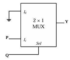
Correct : a
Similar Questions
In the circuit shown, diodes D1, D2 and D3 are ideal, and the inputs E1, E2 and E3 are "0 V" for logic '0' and "10 V" for logic '1'. What logic gate does the ci...
A universal logic gate can implement any Boolean function by connecting sufficient number of them appropriately. Three gates are shown.
Which one of the foll...
A universal logic gate can implement any Boolean function by connecting sufficient number of them appropriately. Three gates are shown.
Which one of the foll...

Total Unique Visitors
Loading......