EC > GATE 2022 > Two-Port Networks
A linear 2-port network is shown in Fig. (a). An ideal DC voltage source of 10 V is connected across Port 1. A variable resistance R is connected across Port 2. As R is varied, the measured voltage and current at Port 2 is shown in Fig. (b) as a V2 versus −I2 plot. Note that for V2 = 5 V, I2 = 0 mA, and for V2 = 4 V, I2 = −4 mA.
When the variable resistance R at Port 2 is replaced by the load shown in Fig. (c), the current I2 is _______ mA (rounded off to one decimal place).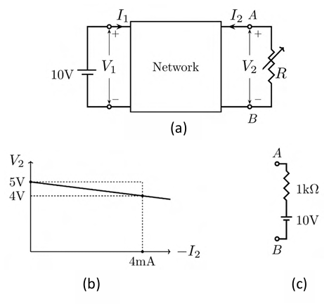
When the variable resistance R at Port 2 is replaced by the load shown in Fig. (c), the current I2 is _______ mA (rounded off to one decimal place).
Correct : -3.3
Similar Questions
For the two port network shown below, the value of the Y21 parameter (in Siemens) is
For the two port network shown below, the [Y]-parameters is given as
The value of load impedance ZL, in Ω, for maximum power transfer will be ____ (rounded off...
The h-parameters of a two port network are shown below. The condition for the maximum small signal voltage gain Vout/Vs is

Total Unique Visitors
Loading......