EC > GATE 2022 > MOSFET
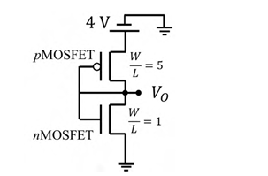
Consider the CMOS circuit shown in the figure (substrates are connected to their respective sources). The gate width (W) to gate length (L) ratios (W/L) of the transistors are as shown. Both the transistors have the same gate oxide capacitance per unit area. For the pMOSFET, the threshold voltage is −1 V and the mobility of holes is 40 cm2/(V.s). For the nMOSFET, the threshold voltage is 1 V and the mobility of electrons is 300 cm2/(V.s). The steady state output voltage VO is ________.
Correct : b
Similar Questions
An NMOS transistor operating in the linear region has IDS of 5 μA at VDS of 0.1 V.
Keeping VGS constant, the VDS is increased to 1.5 V.
Given that μnCox(W/L)...
The ideal long channel nMOSFET and pMOSFET devices shown in the circuits have threshold voltages of 1 V and −1 V, respectively. The MOSFET substrates are connec...
Consider an ideal long channel nMOSFET (enhancement-mode) with gate length 10 μm and width 100 μm. The product of electron mobility (μn) and oxide capacitance p...

Total Unique Visitors
Loading......