EC > GATE 2022 > Network Analysis
The current I in the circuit shown is ________.
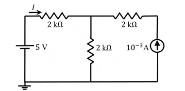
Correct : 1.25 × 10⁻³ a
Similar Questions
Consider a part of an electrical network as shown below. Some node voltages, and the current flowing through the 3Ω resistor are as indicated.The voltage...
Consider the circuit shown in the figure. The current I flowing through the 10 Ω resistor is _______
For the circuit shown, the locus of the impedance Z(jω) is plotted as ω increases from zero to infinity. The values of R1 and R2 are:

Total Unique Visitors
Loading......