EC > GATE 2018 > Zener Diode
The circuit shown in the figure is used to provide regulated voltage (5 V) across the 1KΩ resistor. Assume that the Zener diode has a constant reverse breakdown voltage for a current range, starting from a minimum required Zener current, IZmin=2mA to its maximum allowable current. The input voltage VI may vary by 5% from its nominal value of 6 V. The resistance of the diode in the breakdown region is negligible.
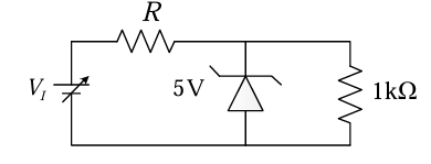 The value of R and the minimum required power dissipation rating of the diode, respectively, are
Correct : b
Similar Questions
As shown in the circuit, the initial voltage across the capacitor is 10 V, with the switch being open.The switch is then closed at t=0.The total energy dissipat...
In the circuit shown, the breakdown voltage and the maximum current of the Zener diode are 20 V and 60 mA, respectively. The values of R1 and RL are 200 Ω...
In the circuit shown below, the knee current of the ideal Zener diode is 10 mA. To maintain 5 V across RL, the minimum value of RL in Ω and the minimum power ra...

Total Unique Visitors
Loading......