EC > GATE 2018 > Op-Amp Circuits
In the circuit shown below, the op-amp is ideal and Zener voltage of the diode is 2.5 volts. At the input, unit step voltage is applied, i.e. vIN(t)=u(t) volts. Also, at t=0, the voltage across each of the capacitors is zero.
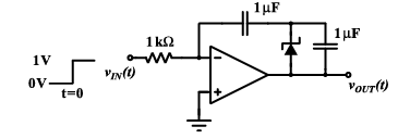 The time t, in milliseconds, at which the output voltage vOUT crosses -10 V is
Correct : c
Similar Questions
The VOUT/VIN of the circuit shown below is
An ideal OPAMP circuit with a sinusoidal input is shown in the figure. The 3 dB frequency is the frequency at which the magnitude of the voltage gain decreases...
For the following circuit with an ideal OPAMP, the difference between the maximum and the minimum values of the capacitor voltage (VC) is __________.

Total Unique Visitors
Loading......