EC > GATE 2016 SET-2 > Op-Amp Circuits
In the opamp circuit shown, the Zener diodes Z1 and Z2 clamp the output voltage V0 to +5 V or -5 V. The switch S is initially closed and is opened at time t=0. The time t=t1 (in seconds) at which V0 changes state is
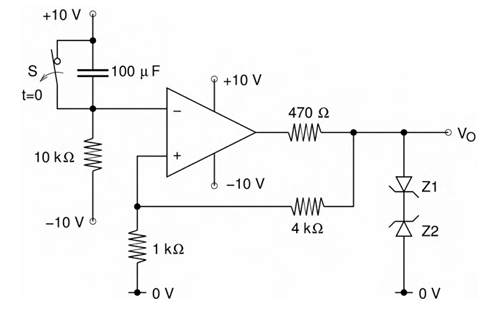
Correct : 0.8
Similar Questions
The VOUT/VIN of the circuit shown below is
An ideal OPAMP circuit with a sinusoidal input is shown in the figure. The 3 dB frequency is the frequency at which the magnitude of the voltage gain decreases...
For the following circuit with an ideal OPAMP, the difference between the maximum and the minimum values of the capacitor voltage (VC) is __________.

Total Unique Visitors
Loading......