EC > GATE 2016 SET-2 > Diode Circuits
The figure shows a half-wave rectifier with a 475 μF filter capacitor. The load draws a constant current I0=1 A from the rectifier. The figure also shows the input voltage Vi, the output voltage VC and the peak-to-peak voltage ripple u on VC. The input voltage Vi is a triangle-wave with an amplitude of 10 V and a period of 1 ms. The value of the ripple u (in volts) is
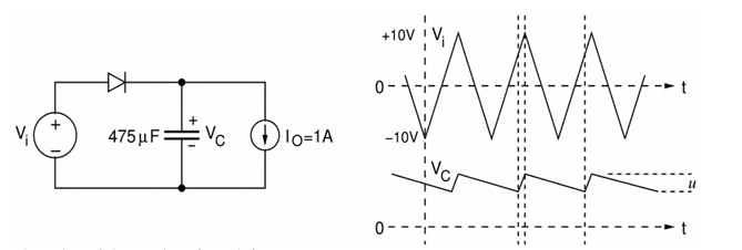
Correct : 2.1
Similar Questions
In the circuit shown, the n: 1 step-down transformer and the diodes are ideal.The diodes have no voltage drop in forward biased condition.If the input voltage (...
In the circuit shown below, D1 and D2 are silicon diodes with cut-in voltage of 0.7 V. VIN and VOUT are input and output voltages in volts. The transfer charact...
All the diodes in the circuit given below are ideal.Which of the following plots is/are correct when VI (in Volts) is swept from -M to M?

Total Unique Visitors
Loading......