EC > GATE 2016 SET-1 > Op-Amp Circuits
An ideal opamp has voltage sources V1,V3,V5,...,VN-1 connected to the non-inverting input and V2, V4,V6,...,VN connected to the inverting input as shown in the figure below (+VCC=15 volt, -Vcc=-15 volt). The voltages V1, V2, V3, V4, V5, V6... are 1, -1/2, 1/3, -1/4, 1/5, -1/6, ... volt, respectively. As N approaches infinity, the output voltage (in volt) is
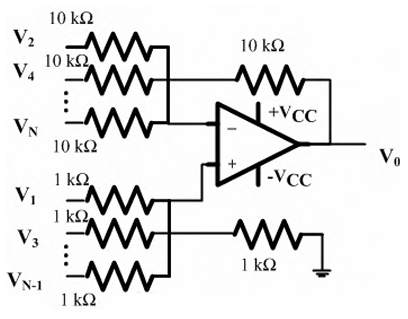
Correct : 15.25
Similar Questions
The VOUT/VIN of the circuit shown below is
An ideal OPAMP circuit with a sinusoidal input is shown in the figure. The 3 dB frequency is the frequency at which the magnitude of the voltage gain decreases...
For the following circuit with an ideal OPAMP, the difference between the maximum and the minimum values of the capacitor voltage (VC) is __________.

Total Unique Visitors
Loading......