EC > GATE 2015 SET-2 > Digital Circuits
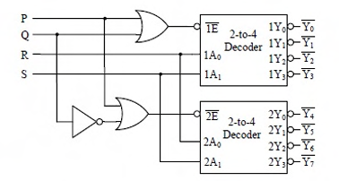
A 1-to-8 demultiplexer with data input Din, address inputs S0, S1, S2 (with S0 as the LSB) and Y0 to Y7 as the eight demultiplexed outputs, is to be designed using two 2-to-4 decoders (with enable input E and address inputs A0 and A1) as shown in the figure. Din, S0, S1 and S2 are to be connected to P, Q, R and S, but not necessarily in this order. The respective input connections to P, Q, R, and S terminals should be
Correct : d
Similar Questions
In an 8085 microprocessor, the shift registers which store the result of an arithmetic operation and the overflow bit, respectively, are
A 16 KB (16 × 210 bytes) memory array is designed as a square with an aspect ratio of one (number of rows is equal to the number of columns). The minimum...
A 3-input majority gate is defined by the logic function M(a,b,c) = ab + bc + ca. Which one of the following gates is represented by the function [M(M(a,b,c),M(...

Total Unique Visitors
Loading......